Low-Voltage Distribution System Lightning Protection & Earthing Design Guide
A comprehensive engineering guide for 10kV and below power distribution systems, providing complete lightning protection and earthing design solutions to safeguard personnel, ensure equipment continuity, and suppress ground potential rise in substations, data centers, industrial facilities, and commercial buildings.
System Overview
Low-voltage distribution system lightning protection and earthing (LPE) design provides comprehensive defense against direct lightning strikes, induced surges, and lightning electromagnetic pulses (LEMP) for power systems rated 10kV and below. The core objectives are to protect personnel safety, ensure continuous equipment operation, and suppress ground potential rise through multi-level protection and low-impedance grounding networks. This guide addresses typical applications including 10kV/0.4kV transformer substations, distribution rooms, UPS systems, and precision load protection.
Modern LPE solutions integrate external lightning protection systems (air terminals, down conductors, grounding electrodes) with internal surge protection devices (SPDs) deployed in coordinated cascades at service entrance, distribution, and equipment levels. These systems safely conduct lightning currents to earth while clamping transient overvoltages below equipment withstand levels, protecting transformers rated 100kVA-5000kVA, low-voltage switchgear, motor control centers, and sensitive electronic loads in industrial, commercial, and data center environments.
This guide provides a complete engineering framework for designing, implementing, and maintaining lightning protection and earthing systems for low-voltage distribution applications. It addresses system architecture, component selection, risk assessment, coordination with building grounding and other MEP systems, installation standards per GB 50057 and GB/T 50343, and lifecycle maintenance to deliver reliable protection with 99.99% availability throughout the facility operational life.
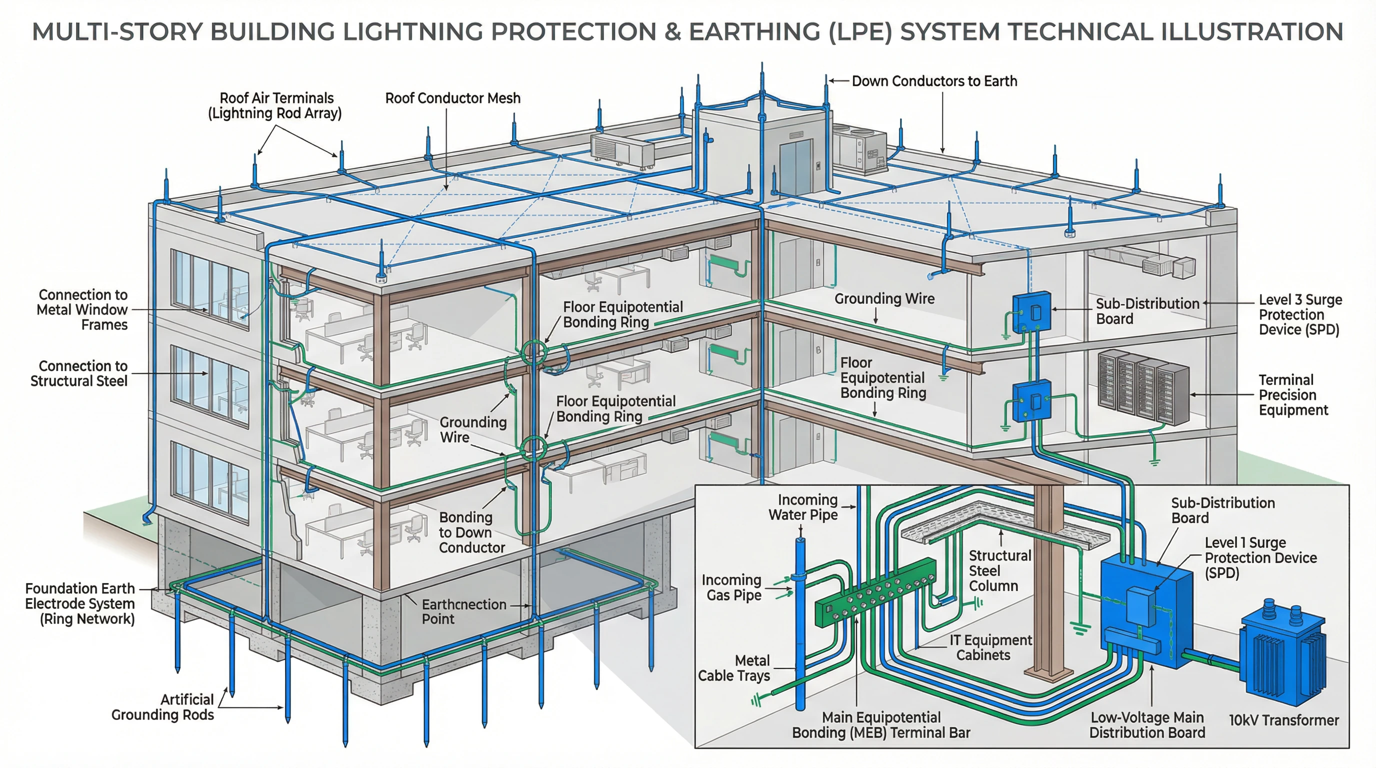
Figure 1.1: Low-Voltage Distribution System Lightning Protection & Earthing (LPE) Technical Architecture
Core Capabilities
The low-voltage distribution system LPE delivers comprehensive protection through six integrated functional modules that work together to ensure personnel safety, equipment reliability, and operational continuity. Each capability addresses specific protection requirements while contributing to the overall system effectiveness for 10kV and below power systems.
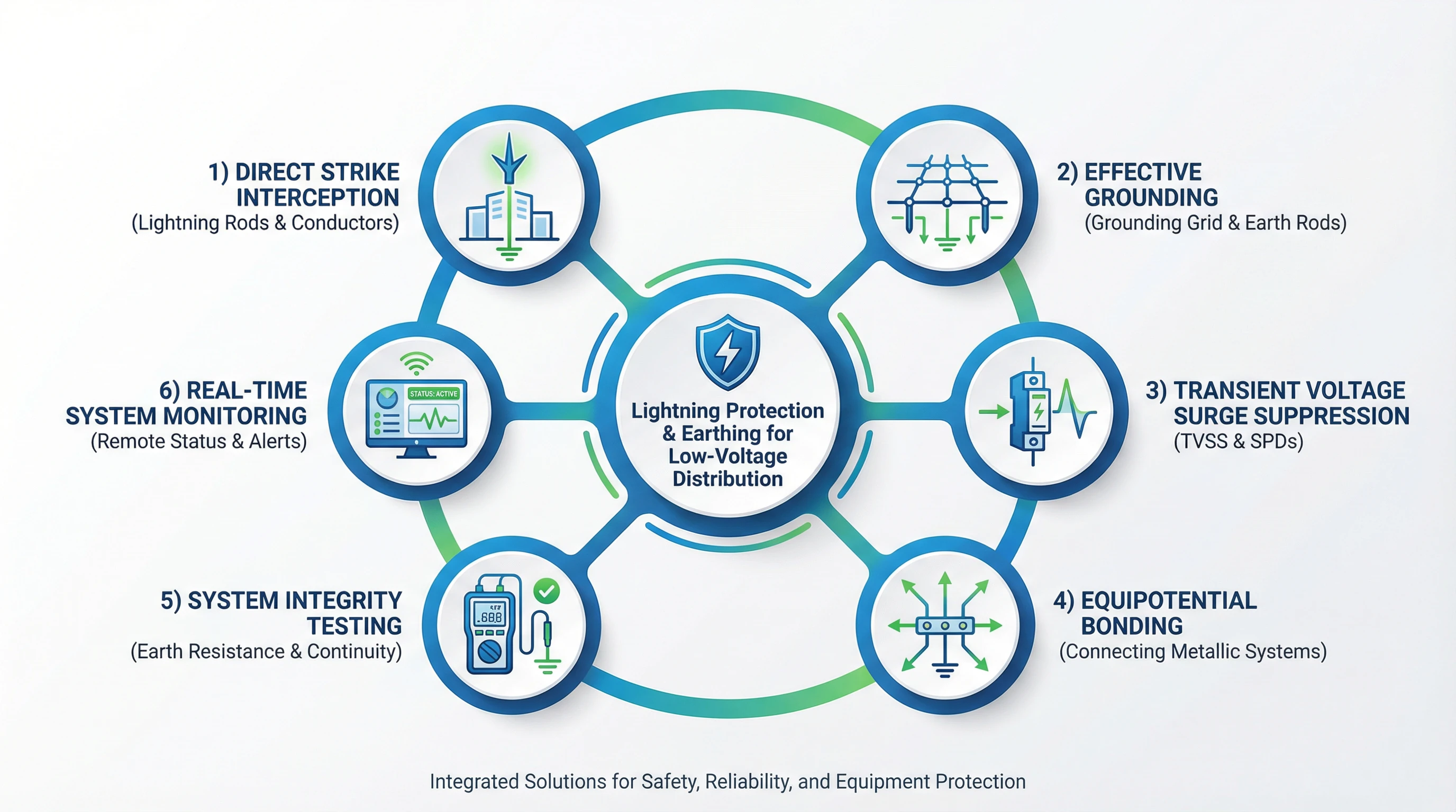
Figure 1.2: Low-Voltage Distribution System LPE Core Function Relationship Diagram
Direct Strike Interception
The air terminal system attracts and intercepts direct lightning strikes, channeling massive lightning currents safely into the earth through down conductors. This capability serves as the first line of defense, protecting building structures and electrical equipment from fire, explosion, and structural damage. Implementation relies on rolling sphere method calculations to determine protection coverage, with down conductor spacing and specifications conforming to GB 50057 standards. Acceptance testing focuses on air terminal material quality, welding integrity, corrosion protection, and grounding resistance values.
Effective Grounding
A unified grounding system utilizing building foundation reinforcement combined with artificial grounding electrodes provides a stable, low-impedance common grounding reference for the low-voltage distribution system. This capability creates pathways for lightning current dissipation, equipment working ground, and static discharge, effectively reducing ground potential rise to protect 10kV/0.4kV transformers and downstream equipment. Implementation leverages foundation reinforcement as natural grounding bodies, supplemented with vertical grounding electrodes when necessary to ensure network continuity. Acceptance testing verifies grounding resistance values (typically ≤1Ω for critical facilities or ≤4Ω for general applications per GB 50065) and grounding network continuity.
Transient Voltage Surge Suppression
Surge Protective Devices (SPDs) installed in cascaded levels on power and signal lines clamp induced lightning or switching overvoltages to equipment-safe levels. This capability protects sensitive electrical and electronic equipment in low-voltage distribution systems from damage, serving as the core of internal protection. Implementation requires energy coordination between levels (Level 1 at service entrance for energy discharge, Level 2 at distribution panels for voltage limiting, Level 3 at equipment terminals for fine protection), correct selection of parameters (In, Imax, Up) per IEC 61643-11, and short, thick connection conductors. Acceptance testing examines SPD installation locations, connection conductor length and gauge, Up value testing, and status indication.
Equipotential Bonding
All metallic installations, extraneous conductive parts, and electrical circuit grounding bodies in the low-voltage distribution system are connected at the Main Equipotential Bonding (MEB) or Local Equipotential Bonding (LEB) terminals to form an equipotential network. This capability eliminates dangerous potential differences between different metallic components during lightning events or power faults, preventing flashover and electric shock hazards. Implementation utilizes S-type (star) or M-type (mesh) structures with copper braided straps or BV conductors for reliable connections per GB/T 50343. Acceptance testing measures connection point continuity resistance (<0.03Ω) and conductor cross-sectional area.
Intelligent Monitoring and Alarming
Real-time monitoring of SPD degradation status, grounding resistance values, and lightning strike counts with data upload to monitoring centers enables predictive maintenance, early fault warning, and enhanced operational efficiency and system reliability for low-voltage distribution facilities. Implementation requires SPDs with remote signaling contacts, installation of online monitoring instruments, and integration with building automation or SCADA systems. Acceptance testing verifies proper remote signal triggering and reception, monitoring data accuracy, and alarm linkage functionality.
Maintainability and Testability
Design provisions for test points, modular replacement components, and clear identification facilitate daily inspections and post-fault recovery in low-voltage distribution systems. This capability shortens Mean Time To Repair (MTTR) and reduces long-term operational costs and complexity. Implementation includes dedicated grounding test wells, modular plug-in SPDs, and clearly labeled grounding conductors per GB 50303 requirements. Acceptance testing evaluates test point accessibility, identification system completeness, and spare part replacement workspace adequacy.