Safety and Risks
6.1 Risk Assessment Framework
Systematic risk assessment identifies potential failure modes, evaluates their likelihood and consequences, and prioritizes mitigation measures to achieve acceptable risk levels. The assessment process considers both the probability of lightning events and the vulnerability of protected assets, recognizing that effective risk management requires addressing both threat frequency and consequence severity. Quantitative risk assessment methods enable objective comparison of different protection strategies and support cost-benefit analysis of protection investments.
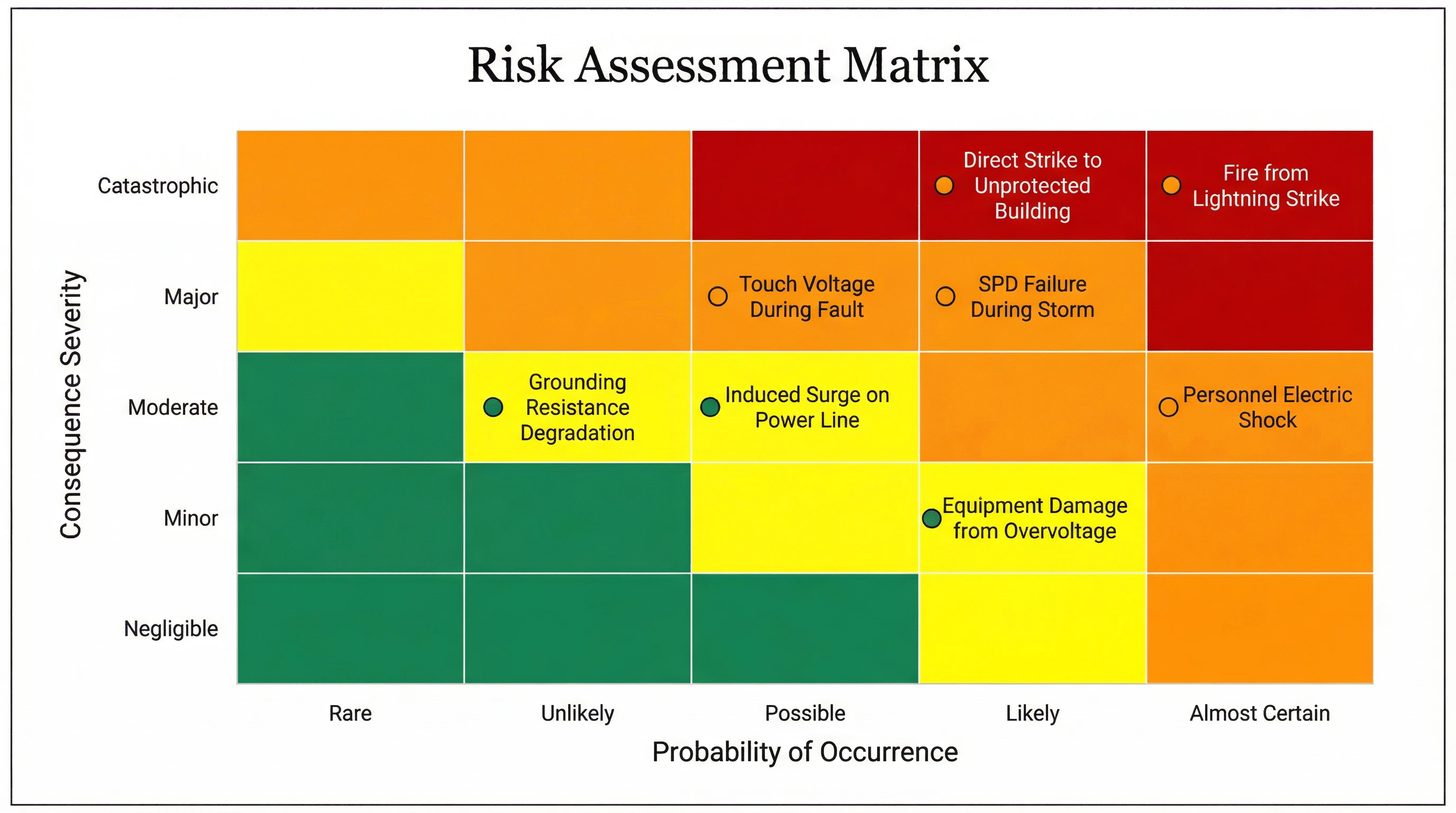
Figure 6.1: Lightning Protection Risk Assessment Matrix Showing Consequence Severity vs. Probability of Occurrence
Probability Assessment
Lightning strike probability depends on geographic location, building dimensions, and surrounding terrain. The annual number of dangerous events (ND) can be estimated from local ground flash density (Ng, flashes per km² per year), building dimensions, and location factors. Tall buildings in exposed locations experience higher strike probability than low structures in urban areas. Historical lightning detection network data provides actual strike frequency for existing facilities, enabling validation of calculated probabilities and identification of localized high-risk areas.
Consequence Evaluation
Consequence severity assessment considers potential losses including personnel injury or death, physical damage to structures and equipment, business interruption costs, and loss of irreplaceable data or cultural assets. Quantitative assessment assigns monetary values to each loss category, while qualitative methods employ severity scales (negligible, minor, moderate, major, catastrophic) based on organizational risk tolerance. Critical facilities housing essential services or hazardous materials warrant higher protection levels due to elevated consequence severity regardless of strike probability.
| Risk Category | Threat Description | Typical Probability | Potential Consequences | Primary Mitigation | Secondary Mitigation |
|---|---|---|---|---|---|
| Direct Strike | Lightning channel terminates on building or connected services | Likely (exposed structures) | Fire, structural damage, equipment destruction, personnel injury | External LPS (air terminals, down conductors, grounding) | Fire detection and suppression, structural reinforcement |
| Induced Surge | Electromagnetic coupling from nearby strike induces overvoltage | Almost Certain (all facilities) | Equipment damage, data loss, process interruption | Coordinated SPD cascade, equipotential bonding | Equipment surge immunity, data backup |
| Ground Potential Rise | Lightning current elevates local earth potential | Likely (during direct strike) | Touch/step voltage hazards, equipment damage via ground loops | Low grounding resistance, equipotential bonding | Insulating surfaces, restricted access during storms |
| SPD Failure | Protection device reaches end of life or suffers catastrophic failure | Possible (aging systems) | Loss of protection, potential fire from failed device | Regular inspection, predictive replacement | Remote monitoring, backup protection, thermal cutoffs |
| Grounding Degradation | Corrosion or soil changes increase grounding resistance | Unlikely (proper materials) | Reduced protection effectiveness, elevated touch voltages | Corrosion-resistant materials, periodic testing | Soil treatment, electrode augmentation |
6.2 Personnel Safety Considerations
Lightning protection system design must address personnel safety hazards including electric shock from touch and step voltages, arc flash from protection device operation, and physical hazards from installation and maintenance activities. Safety measures integrate into system design rather than being added as afterthoughts, recognizing that personnel protection represents the highest priority in protection system hierarchy. Compliance with electrical safety standards and implementation of administrative controls supplement engineering measures to achieve comprehensive personnel protection.
Touch and Step Voltage Hazards
During lightning events or power system faults, current flow through the grounding system creates voltage gradients in the earth that can expose personnel to dangerous touch voltages (between grounded object and earth) or step voltages (between feet separated by one pace). Touch voltage typically presents greater hazard due to current path through vital organs when a person contacts a grounded structure while standing on earth at different potential. Mitigation measures include low grounding resistance to limit ground potential rise, equipotential bonding to eliminate potential differences between accessible metallic components, and high-resistivity surface layers (crushed stone, asphalt) to increase contact resistance between feet and earth.
Arc Flash Considerations
SPD operation, particularly during end-of-life failure modes, can generate arc flash hazards that expose personnel to thermal energy and blast pressure. Proper SPD installation includes adequate working clearance per electrical safety standards, arc-rated enclosures that contain arc energy, and remote indication to enable status verification without enclosure access. Maintenance procedures require arc-rated personal protective equipment when working on energized equipment, with arc flash hazard analysis determining required protection levels based on available fault current and clearing time.
Installation and Maintenance Safety
Lightning protection system installation and maintenance activities present conventional electrical and construction hazards including falls from elevation, electrical shock from contact with energized conductors, and struck-by hazards from tools or materials. Safety programs address these hazards through proper training, personal protective equipment, lockout-tagout procedures for electrical isolation, and fall protection systems for work at elevation. Weather monitoring protocols suspend outdoor work during thunderstorm conditions when lightning risk to workers becomes unacceptable.
6.3 Equipment Protection Strategies
Equipment protection strategies employ multiple defensive layers that address different threat mechanisms and provide redundancy against single-point failures. Defense-in-depth approaches recognize that no single protection measure provides complete immunity, requiring coordinated application of multiple techniques to achieve acceptable equipment survival probability. Protection strategy development considers equipment vulnerability characteristics, replacement cost, and business impact of equipment failure to optimize protection investments.
Surge Immunity Enhancement
Equipment surge immunity represents the voltage level that equipment can withstand without damage, typically specified in product standards for different equipment categories. Industrial equipment generally exhibits higher immunity (2-4kV) than sensitive electronics (1-1.5kV), influencing required SPD protection levels. Equipment selection can enhance overall system robustness by specifying products with higher surge immunity ratings, reducing dependence on external protection and improving tolerance of protection system imperfections. Immunity testing per IEC 61000-4-5 verifies equipment capability under standardized surge conditions.
Isolation and Filtering
Isolation transformers and line filters provide additional protection layers between SPDs and sensitive equipment, attenuating high-frequency transients that SPDs may not fully suppress. Isolation transformers with electrostatic shields between primary and secondary windings block common-mode surges while maintaining power transfer, proving particularly effective for single-phase equipment. EMI filters employing series inductors and shunt capacitors create low-pass filters that attenuate fast transients, complementing SPD protection that primarily addresses lower-frequency surge components. Combined SPD and filter approaches deliver superior protection compared to either technique alone.
Redundancy and Backup
Critical equipment protection strategies incorporate redundancy to maintain operation despite component failures. N+1 redundancy provides spare capacity to accommodate single-component failure, while 2N redundancy employs completely independent parallel systems. Backup systems may remain offline until needed (cold standby), operate at reduced capacity (warm standby), or share load continuously (hot standby), with selection driven by recovery time objectives and cost constraints. Uninterruptible power supplies provide both surge protection and power continuity, addressing multiple failure modes through a single system.
6.4 Business Continuity Planning
Lightning-related disruptions can impact business operations through equipment damage, data loss, or extended downtime for repairs. Business continuity planning identifies critical functions, establishes recovery objectives, and implements measures to maintain operations or enable rapid recovery following lightning events. Effective planning integrates lightning protection with broader business continuity and disaster recovery programs, recognizing that lightning represents one of multiple threats requiring coordinated mitigation strategies.
Impact Analysis
Business impact analysis quantifies the consequences of lightning-related disruptions across different time scales from immediate equipment failure through extended outages. Analysis identifies critical processes that cannot tolerate interruption, dependencies between systems that could propagate failures, and recovery time objectives that determine acceptable downtime. Financial impact assessment includes direct costs (equipment replacement, repair labor) and indirect costs (lost revenue, customer dissatisfaction, regulatory penalties) to support investment decisions for protection and recovery capabilities.
Recovery Strategies
Recovery strategies define the approach to restoring operations following lightning-related disruptions. Strategies may emphasize rapid equipment replacement through spare parts inventory and vendor agreements, alternative processing sites that can assume critical functions, or degraded-mode operation using manual processes or reduced capacity. Recovery time objectives drive strategy selection, with shorter objectives requiring more extensive (and costly) preparation including hot standby systems, comprehensive spare parts, and pre-positioned recovery teams. Regular testing validates recovery capability and identifies planning gaps requiring correction.
| Impact Scenario | Typical Recovery Time | Business Impact | Mitigation Priority | Recommended Actions |
|---|---|---|---|---|
| Single SPD Failure | 1-4 hours | Low (redundant protection remains) | Medium | Spare parts inventory, rapid response procedures |
| Server/Network Equipment Damage | 4-24 hours | High (service interruption) | High | Comprehensive SPD protection, equipment redundancy, backup systems |
| Power Distribution Failure | 8-48 hours | Severe (facility offline) | Critical | Robust primary protection, backup power, alternative site capability |
| Grounding System Damage | 1-7 days | Moderate (reduced protection) | Medium | Quality materials and installation, periodic testing, repair procedures |
| Fire from Lightning Strike | Weeks to months | Catastrophic (facility destruction) | Critical | External LPS, fire detection/suppression, insurance, disaster recovery site |