Tools and Auxiliary Materials
8.1 Installation Tools and Equipment
Proper installation of lightning protection and earthing systems requires specialized tools and equipment that ensure connections meet electrical and mechanical performance requirements. Tool selection impacts installation quality, worker safety, and project efficiency. Understanding tool capabilities, proper usage techniques, and maintenance requirements enables contractors to deliver installations that meet design specifications and provide reliable long-term performance.
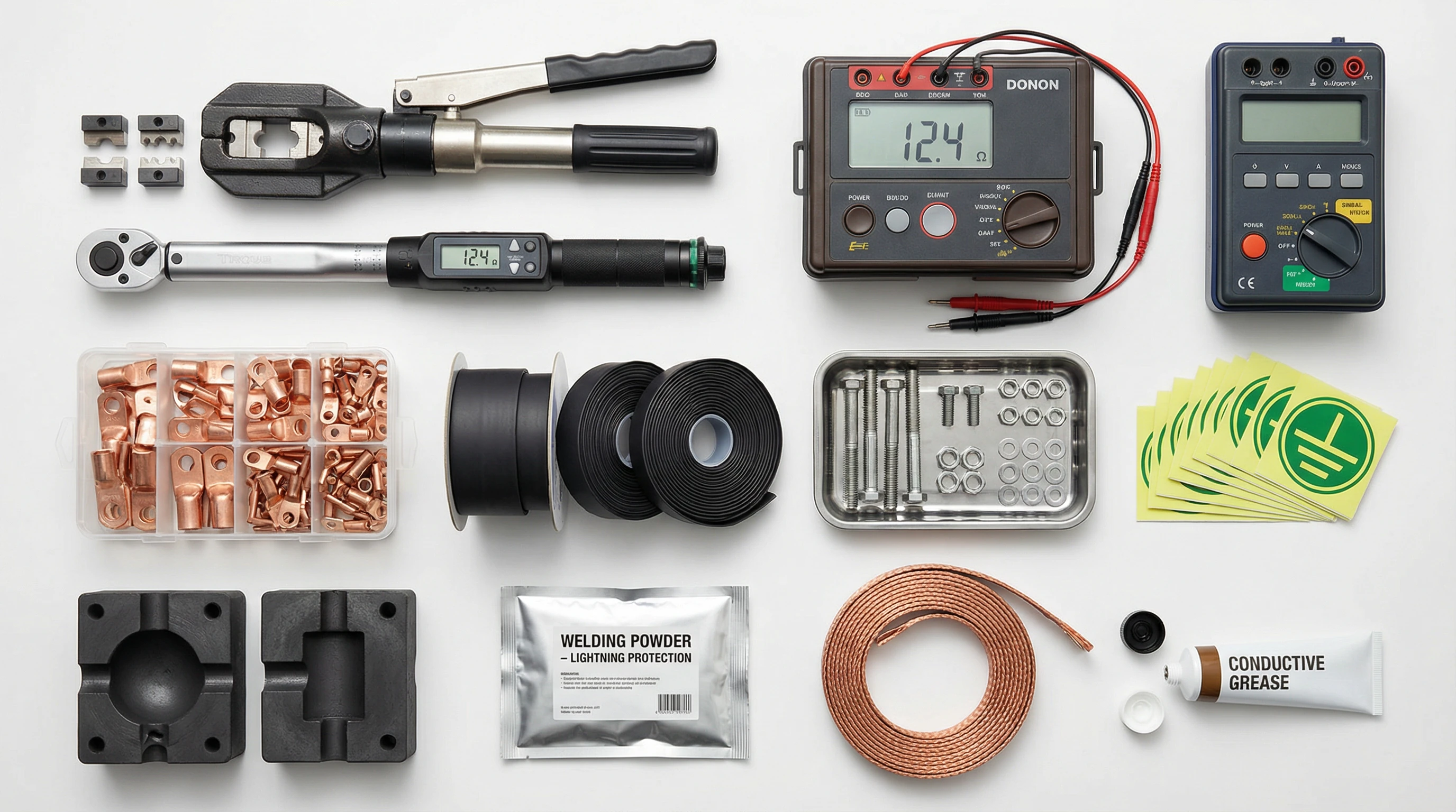
Figure 8.1: Lightning Protection Installation Tools and Accessories Photographic Reference
Connection and Termination Tools
Hydraulic crimping tools create reliable compression connections between conductors and terminals, applying controlled force that ensures proper conductor deformation without damage. Tool selection must match lug and conductor sizes, with dies appropriate for the specific terminal type and conductor material. Battery-powered hydraulic tools provide portability for field installations, while bench-mounted units offer higher force capacity for large conductors. Proper crimping technique requires full die closure and verification of crimp dimensions using go/no-go gauges to ensure connection quality.
Torque wrenches ensure that bolted connections achieve specified clamping force without over-tightening that could damage terminals or strip threads. Beam-type torque wrenches provide simple, reliable operation for general applications, while click-type or digital models offer improved accuracy for critical connections. Torque specifications vary by fastener size, material, and application, requiring reference to manufacturer data or applicable standards. Proper technique includes applying torque in a smooth, continuous motion perpendicular to the wrench handle, avoiding impact or jerking that could produce inaccurate results.
Grounding Electrode Installation Equipment
Ground rod drivers employ pneumatic, hydraulic, or electric power to drive vertical electrodes into soil with minimal physical effort and reduced risk of electrode damage. Pneumatic drivers offer high impact energy suitable for dense soils, while electric rotary-percussion drivers provide quieter operation appropriate for occupied buildings. Driver selection must match electrode diameter and length, with proper technique maintaining vertical alignment throughout the driving process. Safety equipment including hearing protection, safety glasses, and steel-toed boots protects workers from noise, flying debris, and dropped electrodes.
Exothermic welding equipment creates permanent, low-resistance connections through controlled chemical reactions that produce molten copper. Complete kits include graphite molds matched to conductor sizes and connection configurations, welding powder charges, ignition systems, and safety equipment. Proper technique requires thorough conductor cleaning, correct mold positioning and clamping, appropriate charge selection, and safe ignition from a distance using the provided ignition system. Mold preheating in damp conditions prevents moisture-related weld defects, while post-weld inspection verifies complete conductor fusion and absence of voids.
| Tool Category | Typical Tools | Primary Applications | Key Selection Criteria | Safety Considerations |
|---|---|---|---|---|
| Crimping Tools | Hydraulic crimper, dies, go/no-go gauges | Lug terminations, conductor splices | Force capacity, die compatibility, portability | Pinch points, hydraulic pressure |
| Torque Tools | Torque wrench, socket sets | Bolted connections, terminal blocks | Torque range, accuracy, calibration | Over-torque damage, proper technique |
| Driving Equipment | Ground rod driver, couplings, driving points | Vertical electrode installation | Power type, impact energy, electrode compatibility | Noise, vibration, struck-by hazards |
| Welding Equipment | Exothermic welding kit, molds, powder | Permanent conductor connections | Mold inventory, charge types, ignition method | Molten metal, fire hazard, fumes |
| Cutting Tools | Cable cutters, hacksaws, grinding wheels | Conductor sizing, electrode trimming | Cutting capacity, blade type, power source | Sharp edges, flying debris, noise |
8.2 Testing and Measurement Instruments
Verification of lightning protection system performance requires specialized test equipment capable of measuring electrical parameters under field conditions. Instrument selection must provide adequate accuracy, range, and features for the specific measurement application while maintaining calibration traceability to national standards. Proper measurement technique and result interpretation ensure that test data accurately reflects system performance and compliance with design requirements.
Earth Resistance Testing
Earth resistance testers measure the resistance between grounding electrodes and remote earth using three-pole or four-pole test methods. Three-pole testing employs two auxiliary electrodes positioned at specified distances from the electrode under test, with the instrument injecting test current and measuring voltage drop to calculate resistance. Four-pole testing adds a fourth electrode to eliminate lead resistance from measurements, providing improved accuracy for low-resistance systems. Clamp-on earth resistance testers enable testing without disconnecting grounding conductors or driving auxiliary electrodes, though they require complete grounding loops and may exhibit reduced accuracy compared to conventional methods.
Proper test technique requires auxiliary electrode placement at distances sufficient to eliminate mutual interference, typically 20-30 meters for building grounding systems. Test current frequency selection avoids interference from power frequency currents and harmonics, with most instruments employing frequencies between 94Hz and 160Hz. Multiple measurements at different auxiliary electrode positions verify result consistency and identify measurement errors caused by underground utilities or soil inhomogeneities. Seasonal variations in soil moisture affect resistance measurements, requiring periodic retesting or application of correction factors to normalize results.
Continuity and Bonding Verification
Low-resistance ohmmeters measure connection resistance between bonded components to verify equipotential bonding effectiveness. These instruments employ four-wire measurement techniques that eliminate test lead resistance, providing accurate measurements of resistances below 0.1Ω. Test current typically ranges from 10mA to 200mA, sufficient to overcome contact resistance without requiring high power consumption. Proper technique includes thorough cleaning of test points to remove oxidation and paint, firm probe contact, and multiple measurements to verify result repeatability.
Continuity testing of down conductors and grounding conductors verifies that connections maintain electrical integrity throughout the system. Megohmmeter testing confirms insulation resistance of SPD disconnectors and verifies that isolation barriers maintain adequate separation between circuits. Proper documentation of test results including test point locations, measured values, test conditions, and instrument identification provides the basis for acceptance decisions and future comparison during maintenance testing.
| Instrument Type | Measurement Parameter | Typical Range | Accuracy Requirement | Application |
|---|---|---|---|---|
| Earth Resistance Tester | Grounding resistance | 0.01Ω - 2000Ω | ±2% of reading | Grounding system acceptance, periodic testing |
| Clamp-On Earth Tester | Loop resistance | 0.1Ω - 100Ω | ±5% of reading | In-service testing, troubleshooting |
| Low-Resistance Ohmmeter | Bonding resistance | 0.001Ω - 20Ω | ±1% ± 3 digits | Equipotential bonding verification |
| Megohmmeter | Insulation resistance | 0.01MΩ - 10GΩ | ±5% of reading | SPD isolation, cable insulation |
| Multimeter | Voltage, current, resistance | Varies by function | ±0.5% typical | General electrical verification |
8.3 Connection Hardware and Accessories
Reliable electrical and mechanical connections require appropriate hardware selected for the specific conductor types, environmental conditions, and performance requirements. Hardware quality directly impacts connection resistance, corrosion resistance, and long-term reliability. Proper selection considers material compatibility, current-carrying capacity, environmental exposure, and installation method to ensure connections maintain performance throughout the system operational life.
Lugs and Terminals
Compression lugs create permanent connections between conductors and equipment terminals through mechanical deformation that produces high contact pressure and low resistance. Copper lugs suit most applications, providing excellent conductivity and compatibility with copper conductors. Aluminum lugs require use with aluminum conductors to prevent galvanic corrosion, with proper joint compound application essential to prevent oxidation. Lug sizing must accommodate conductor cross-section while fitting equipment terminal dimensions, with barrel length sufficient to fully contain the conductor and provide adequate crimp area.
Mechanical lugs employ set screws or bolts to clamp conductors, offering field-adjustable connections suitable for temporary installations or locations requiring frequent disconnection. These terminals require greater installation space than compression lugs and may exhibit higher contact resistance, making them less suitable for high-current or critical applications. Proper installation requires conductor insertion to the full barrel depth, adequate tightening torque per manufacturer specifications, and verification that all strands remain within the terminal barrel.
Bonding Hardware
Bonding clamps connect grounding conductors to structural steel, piping, and other metallic components without requiring drilling or welding. Bronze or stainless steel construction provides corrosion resistance in harsh environments, while copper-plated steel offers economy for indoor applications. Clamp sizing must match the component diameter and conductor size, with serrated contact surfaces penetrating surface oxidation to ensure low-resistance connections. Proper installation requires adequate tightening torque to maintain contact pressure under vibration and thermal cycling.
Grounding lugs and lay-in lugs facilitate connection of multiple conductors at common bonding points. These devices accommodate various conductor sizes and types, providing flexibility for field modifications and additions. Tin-plated or silver-plated contact surfaces reduce oxidation and maintain low contact resistance in humid environments. Installation requires proper torque application and verification that all conductors achieve solid contact with the terminal surface.
8.4 Corrosion Protection Materials
Corrosion of grounding system components degrades electrical performance and mechanical integrity, potentially compromising protection effectiveness. Corrosion protection strategies employ material selection, protective coatings, and cathodic protection techniques appropriate for soil conditions and installation environment. Proper application of corrosion protection measures extends system operational life and reduces maintenance requirements.
Protective Coatings and Compounds
Conductive grease applied to bolted connections prevents oxidation while maintaining electrical conductivity. These compounds contain conductive particles suspended in petroleum or synthetic base materials that exclude moisture and oxygen from connection surfaces. Application requires thorough surface cleaning followed by generous compound application to all contact surfaces before assembly. Periodic reapplication during maintenance activities maintains protection effectiveness.
Anti-corrosion tape and heat-shrink tubing protect above-ground connections from moisture and atmospheric corrosion. Mastic-backed tape conforms to irregular surfaces and provides self-sealing properties, while heat-shrink tubing offers superior mechanical protection and environmental sealing. Proper application requires surface cleaning and degreasing, adequate overlap for tape applications, and complete shrinking for heat-shrink products. Color-coding aids system identification and facilitates future maintenance activities.
Cathodic Protection Integration
Facilities employing impressed current or sacrificial anode cathodic protection for underground piping or storage tanks must coordinate with lightning protection grounding systems to prevent interference. Isolation joints or insulating flanges separate protected structures from building grounding systems, requiring bonding jumpers with surge protection to maintain lightning protection while preserving cathodic protection effectiveness. Proper design requires consultation with corrosion specialists to ensure compatibility between protection systems.
| Material Type | Composition | Application | Advantages | Limitations |
|---|---|---|---|---|
| Conductive Grease | Zinc or copper particles in petroleum base | Bolted connections, terminals | Maintains conductivity, excludes moisture | Requires periodic reapplication |
| Anti-Corrosion Tape | PVC or polyethylene with mastic backing | Above-ground connections, splices | Conformable, self-sealing, economical | UV degradation, limited mechanical protection |
| Heat-Shrink Tubing | Cross-linked polyolefin with adhesive liner | Cable terminations, connection protection | Excellent sealing, mechanical protection | Requires heat source, not reusable |
| Epoxy Coating | Two-part epoxy resin system | Buried connections, harsh environments | Excellent corrosion resistance, durable | Difficult to remove, inspection challenges |
| Galvanizing | Zinc coating on steel substrate | Structural components, hardware | Factory-applied, long service life | Field damage requires repair |
8.5 Documentation and Labeling Materials
Comprehensive system documentation and clear component labeling facilitate installation verification, future maintenance, and troubleshooting activities. Documentation materials must withstand field conditions while remaining legible throughout the system operational life. Proper documentation practices create permanent records that support system management and regulatory compliance.
Identification Labels and Tags
Grounding conductor labels identify conductor function, connection points, and circuit designation using durable materials resistant to environmental exposure. Adhesive labels suit indoor applications, while embossed or engraved tags provide superior durability for outdoor or harsh environments. Color-coding per national standards (green-yellow for protective earth) aids rapid identification, while alphanumeric designations link physical components to system documentation.
SPD status indicators provide visual indication of device operational status, alerting maintenance personnel to failed devices requiring replacement. LED indicators offer low power consumption and long service life, while mechanical flag indicators provide status indication without requiring power. Remote status monitoring through building automation or dedicated monitoring systems enables proactive maintenance and reduces inspection labor requirements.
As-Built Documentation
As-built drawings record actual installed conditions including any field modifications to design documents. These drawings identify grounding electrode locations and depths, down conductor routing, SPD locations and ratings, bonding connection points, and test point locations. Digital documentation in CAD format facilitates future modifications and integration with building information modeling (BIM) systems. Proper documentation practices require field verification of all dimensions and specifications before finalizing as-built records.
Test reports document acceptance testing results and establish baseline values for future comparison during periodic maintenance testing. Reports include test instrument identification and calibration status, test conditions (weather, soil moisture), measured values with acceptance criteria, and photographic documentation of key components and connections. Proper report organization facilitates regulatory review and provides clear evidence of system compliance with design requirements and applicable standards.