Quality and Acceptance
10.1 Material Quality Control
Material quality directly impacts lightning protection system performance, reliability, and service life. Comprehensive quality control programs verify that materials meet design specifications and applicable standards before installation. Quality control activities span manufacturer certification, incoming inspection, storage management, and installation verification to ensure that only conforming materials enter the completed system.
Manufacturer Certification and Documentation
Lightning protection system components require certification to relevant product standards including IEC 62561 series for external protection components and IEC 61643 series for surge protective devices. Manufacturer documentation must include test reports demonstrating compliance with applicable standards, material certificates verifying conductor composition and purity, and quality management system certification (ISO 9001 or equivalent). Procurement specifications should mandate provision of complete documentation with material delivery, enabling verification before installation proceeds.
SPD certification requires particular attention due to the critical protection role these devices perform. Type-tested SPDs carry certification demonstrating compliance with voltage protection level (Up), discharge current capacity (In and Imax), and follow current interruption capability. Test reports should document performance under both nominal operating conditions and maximum rated stress conditions. Certification marks from recognized testing laboratories (UL, TÜV, CSA, or equivalent) provide independent verification of manufacturer claims and reduce procurement risk.
Incoming Material Inspection
Visual inspection upon material receipt identifies shipping damage, dimensional discrepancies, and obvious defects before materials enter storage or installation. Inspection procedures should verify conductor dimensions using calibrated measuring tools, examine surface finish for corrosion or coating damage, confirm hardware thread integrity and dimensional accuracy, and validate that SPD ratings match purchase order specifications. Nonconforming materials require segregation and documentation, with disposition (return, repair, or use-as-is) determined through formal review process.
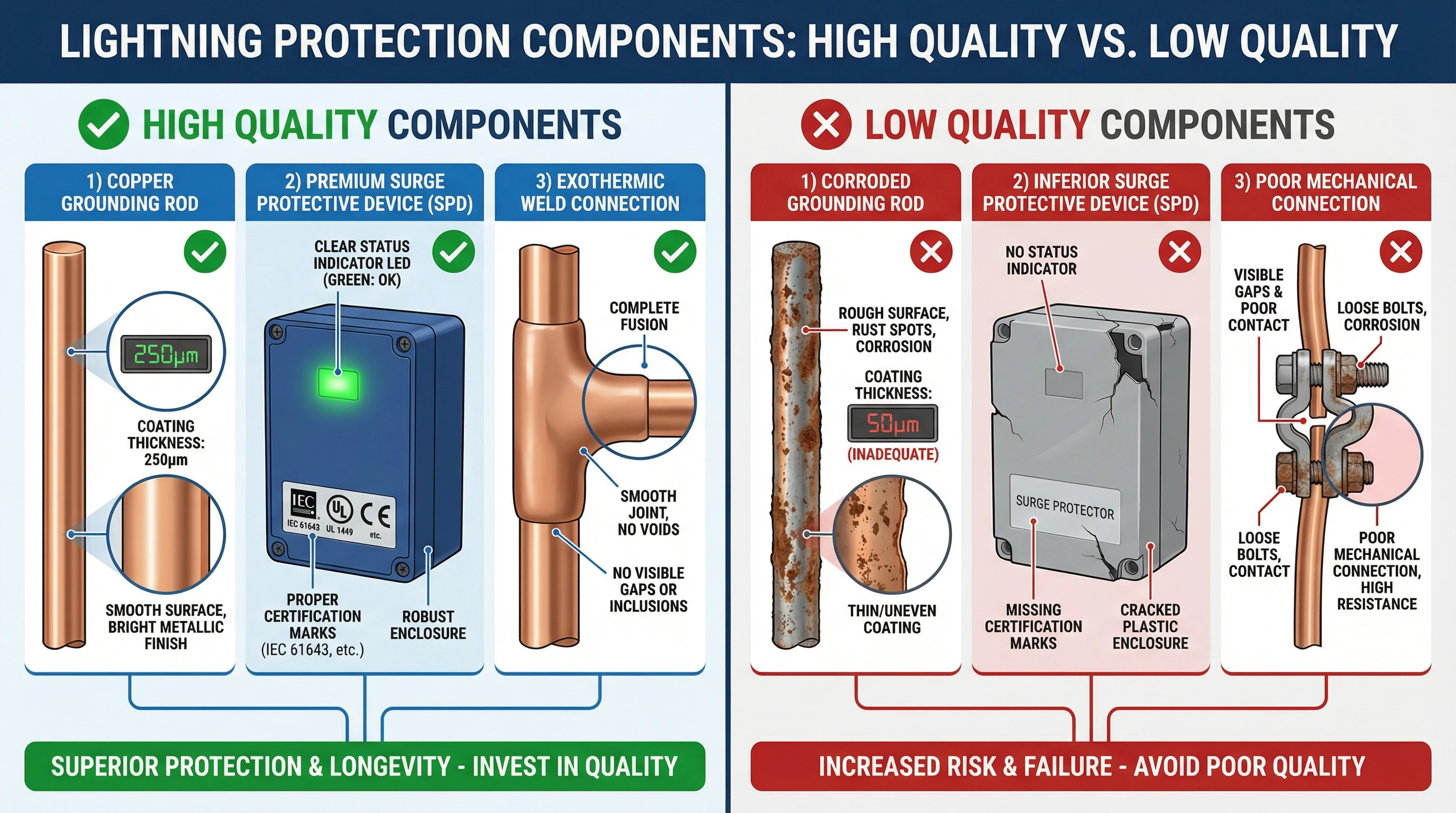
Figure 10.1: Lightning Protection Component Quality Comparison - High Quality vs. Low Quality Materials
| Material Category | Critical Parameters | Inspection Method | Acceptance Criteria | Documentation Required |
|---|---|---|---|---|
| Air Terminals | Material, dimensions, corrosion protection | Visual, dimensional measurement | Per GB 50057 specifications | Material certificate, test report |
| Down Conductors | Cross-section, material purity, coating | Caliper measurement, visual | ≥ specified cross-section | Material certificate, mill test report |
| Grounding Electrodes | Length, diameter, coating thickness | Dimensional check, coating gauge | Per design specifications | Material certificate, coating test |
| SPDs | Uc, In, Imax, Up, response time | Nameplate verification, test report review | Match design specifications exactly | Type test report, IEC 61643 certification |
| Connection Hardware | Material, dimensions, thread quality | Visual, fit check, material verification | Compatible with conductors, corrosion resistant | Material certificate, manufacturer data |
10.2 Installation Quality Verification
Installation quality verification ensures that workmanship meets design intent and applicable standards. Verification activities occur throughout the installation process rather than solely at project completion, enabling early detection and correction of deficiencies. Systematic verification procedures address connection quality, conductor routing, component mounting, and system integration to deliver installations that perform reliably throughout their operational life.
Connection Quality Inspection
Electrical connections represent potential failure points that require thorough inspection to verify mechanical and electrical integrity. Bolted connections require torque verification using calibrated torque wrenches, with torque values documented for critical connections. Crimped connections undergo visual inspection for proper die closure, conductor insertion depth, and absence of strand damage, with go/no-go gauge verification for critical applications. Exothermic welded connections require visual inspection for complete conductor fusion, absence of voids or cracks, and proper mold cleanup.
Bonding connections between grounding conductors and metallic building components require particular attention to ensure low-resistance paths. Inspection verifies that contact surfaces are clean and free of paint or corrosion, bonding hardware is appropriate for conductor and component sizes, and connections achieve specified torque values. Resistance measurement using low-resistance ohmmeters provides quantitative verification of bonding effectiveness, with acceptance criteria typically requiring resistance below 0.03Ω for critical bonds.
Conductor Routing and Support
Down conductor routing inspection verifies compliance with design requirements for conductor spacing, bend radius, and separation from other building systems. Conductors should maintain minimum spacing from metallic building components per lightning protection level requirements, avoid sharp bends that could create high-impedance points or mechanical stress concentrations, and maintain secure attachment to building structure at specified intervals. Routing through building penetrations requires inspection of sealing and firestopping to maintain building envelope integrity.
Grounding conductor routing from SPDs to grounding terminals requires verification of conductor length, routing path, and connection quality. Conductors should follow the shortest practical path to minimize inductive voltage drop, avoid routing parallel to protected circuits to prevent coupling, and maintain adequate mechanical support to prevent damage from vibration or accidental contact. Connection conductor cross-sectional area must meet or exceed specifications based on SPD discharge current rating.
10.3 Electrical Testing and Commissioning
Comprehensive electrical testing verifies that the completed lightning protection system meets design performance requirements and applicable standards. Testing activities progress from component-level verification through subsystem testing to integrated system commissioning. Test results provide objective evidence of system compliance and establish baseline values for future comparison during periodic maintenance testing.
Grounding System Testing
Grounding resistance testing represents the most critical electrical verification activity, confirming that the grounding system achieves specified resistance values. Three-pole fall-of-potential testing provides accurate resistance measurements by injecting test current through auxiliary electrodes positioned at specified distances from the electrode under test. Test procedure requires auxiliary electrode placement at distances sufficient to eliminate mutual interference, typically 20-30 meters for building grounding systems, with measurements repeated at multiple auxiliary electrode positions to verify result consistency.
Soil resistivity measurement using four-pole Wenner method characterizes soil conditions and enables prediction of grounding system performance. Measurements at multiple probe spacings provide resistivity data at various depths, revealing soil stratification that affects electrode performance. Testing should occur under representative soil moisture conditions, with seasonal variations documented to support future troubleshooting and system modifications. Measured resistivity values validate design assumptions and identify locations requiring enhanced grounding measures.
Continuity and Bonding Verification
Continuity testing of down conductors and grounding conductors verifies electrical integrity throughout the system. Low-resistance ohmmeter measurements between system components confirm that connections maintain low impedance, with acceptance criteria typically requiring resistance below 0.1Ω for main conductors. Testing should cover all conductor runs from air terminals to grounding electrodes, equipotential bonding connections between metallic building components, and SPD grounding conductor paths to main grounding terminals.
Equipotential bonding verification measures resistance between bonded metallic components to confirm effective potential equalization. Test points should include structural steel connections to grounding system, HVAC ductwork and piping bonds, fire protection system piping connections, and communication system cable tray bonding. Measured resistance values below 0.03Ω indicate effective bonding, while higher values require investigation and remediation before system acceptance.
| Test Type | Test Method | Acceptance Criteria | Test Frequency | Documentation Required |
|---|---|---|---|---|
| Grounding Resistance | Three-pole fall-of-potential | ≤ 1Ω (critical) or ≤ 4Ω (general) | Initial acceptance, annually | Test report with instrument calibration |
| Conductor Continuity | Low-resistance ohmmeter | < 0.1Ω for main conductors | Initial acceptance, after modifications | Test report with measurement points |
| Bonding Resistance | Four-wire resistance measurement | < 0.03Ω for equipotential bonds | Initial acceptance, every 3 years | Test report with component identification |
| SPD Functionality | Visual inspection, indicator check | Status indicator shows operational | Initial acceptance, quarterly | Inspection checklist, photo documentation |
| Insulation Resistance | Megohmmeter testing | > 1MΩ for isolation barriers | Initial acceptance, after faults | Test report with test voltage noted |
10.4 Documentation and Record Management
Comprehensive documentation creates permanent records of system design, installation, testing, and acceptance that support future maintenance, modifications, and regulatory compliance. Documentation management systems should provide organized storage, ready access, and version control for all project records. Proper documentation practices enable efficient system management throughout the operational lifecycle and facilitate knowledge transfer when personnel changes occur.
As-Built Documentation
As-built drawings record actual installed conditions including any field modifications to design documents. These drawings identify grounding electrode locations with coordinates or dimensioned references to permanent structures, down conductor routing with attachment point locations, SPD locations with ratings and model numbers, bonding connection points with conductor sizes, and test point locations for future access. Digital documentation in CAD format facilitates future modifications and integration with building information modeling (BIM) systems.
Component schedules document all installed materials with manufacturer, model number, rating parameters, installation location, and installation date. SPD schedules prove particularly valuable for maintenance planning, identifying devices requiring periodic inspection or replacement. Grounding electrode schedules record electrode type, dimensions, installation depth, and measured resistance values. Comprehensive schedules enable efficient spare parts management and support future system expansions or modifications.
Test and Inspection Records
Test reports document all acceptance testing activities with test instrument identification and calibration status, test procedures and standards referenced, measured values with acceptance criteria, environmental conditions during testing, and technician identification and qualifications. Photographic documentation supplements written reports, providing visual records of component installation, connection details, and overall system configuration. Digital photography with embedded location data (GPS coordinates) facilitates future component location and condition assessment.
Inspection checklists provide systematic verification that all design requirements and standard provisions have been addressed. Checklists should cover material verification, installation workmanship, electrical testing, safety compliance, and documentation completeness. Completed checklists with inspector signatures provide evidence of thorough review and support acceptance decisions. Nonconformance documentation records any deficiencies identified during inspection, corrective actions taken, and verification of correction effectiveness.
10.5 Acceptance Criteria and Procedures
Formal acceptance procedures verify that the completed lightning protection system meets all design requirements, performance specifications, and applicable standards. Acceptance activities involve review of documentation, verification of test results, visual inspection of completed installation, and functional demonstration of system features. Successful acceptance provides the basis for system turnover to operations and initiates warranty periods for equipment and installation workmanship.
Performance Verification
Performance verification confirms that measured system parameters meet or exceed design specifications. Grounding resistance measurements must achieve specified values under representative soil conditions, with documentation of soil moisture conditions at time of testing. Continuity measurements throughout the system must demonstrate low-resistance paths from air terminals to grounding electrodes. SPD installation must conform to manufacturer requirements for connection conductor length and routing, with verification that voltage protection levels suit protected equipment.
System integration verification demonstrates proper coordination between lightning protection and other building systems. Testing should confirm that equipotential bonding does not create ground loops or interference with sensitive electronic systems, SPD installation does not compromise power quality or create harmonic distortion, and grounding system integration maintains effectiveness of equipment protective earth connections. Functional testing of SPD remote monitoring verifies proper alarm indication and communication with building management systems.
Final Acceptance Process
Final acceptance requires completion of all installation activities, successful completion of all testing with results meeting acceptance criteria, submission of complete documentation including as-built drawings and test reports, correction of all identified deficiencies, and demonstration of proper system operation. Acceptance inspection by qualified third-party inspectors provides independent verification of system compliance and reduces owner risk. Formal acceptance documentation should identify any outstanding items requiring completion during warranty period and establish schedule for first periodic maintenance inspection.