Architecture Design
4.1 Layered Protection Architecture
Modern lightning protection systems employ a layered defense strategy that addresses threats at multiple levels from physical infrastructure through equipment protection to intelligent monitoring. This architectural approach ensures comprehensive protection while maintaining clear separation of concerns and facilitating system expansion and maintenance. Each layer performs specific functions while interfacing with adjacent layers to create an integrated protection envelope that addresses the full spectrum of lightning-related threats.
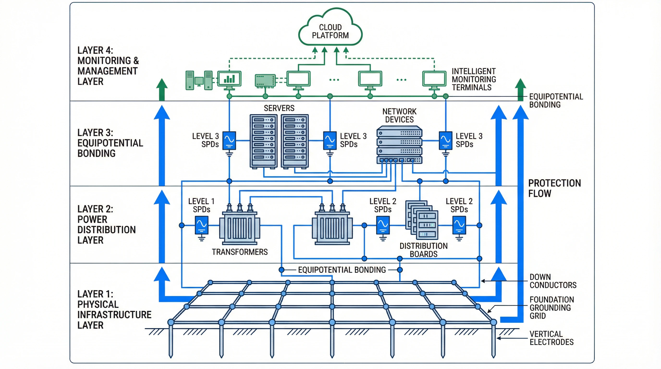
Figure 4.1: Four-Layer Lightning Protection Architecture Showing Protection Flow and Equipotential Bonding
Layer 1: Physical Infrastructure
The physical infrastructure layer establishes the foundation for all protection functions through the grounding system and external lightning protection components. Foundation grounding grids leverage building reinforcement steel to create extensive earth contact, supplemented by vertical electrodes where necessary to achieve target resistance values. Down conductors provide multiple parallel paths for lightning current flow from air terminals to the grounding system, with spacing and routing designed to prevent dangerous magnetic field concentrations or side flashing to building services.
Layer 2: Power Distribution
The power distribution layer implements coordinated surge protection at service entrance and distribution points to prevent overvoltages from reaching sensitive equipment. Level 1 SPDs at utility service entrance points handle direct lightning current components, while Level 2 devices at distribution panels provide intermediate protection with improved voltage limiting performance. Proper coordination between protection levels ensures that each device operates within its design parameters while providing progressively lower residual voltages at successive stages.
Layer 3: Equipment Protection
The equipment protection layer delivers fine protection at terminal equipment through Level 3 SPDs and comprehensive equipotential bonding. These protection measures ensure that residual voltages reaching sensitive electronics remain below equipment withstand capabilities while eliminating dangerous potential differences between interconnected systems. Equipment-level protection must account for the specific vulnerability characteristics of protected devices, including operating voltage ranges, transient immunity levels, and interface types.
Layer 4: Monitoring and Management
The monitoring and management layer provides visibility into protection system status and enables predictive maintenance strategies. Intelligent monitoring terminals track SPD operational status, grounding resistance values, and lightning strike event counts, uploading data to cloud platforms for analysis and long-term trending. This layer transforms the protection system from passive infrastructure into an actively managed asset that supports business continuity planning and risk management objectives.
4.2 Grounding System Architecture
Grounding system architecture determines the effectiveness of all other protection measures by establishing the reference potential for the entire facility and providing low-impedance paths for fault and lightning currents. Effective grounding system design balances the competing requirements of low resistance for safety and lightning protection, stable reference potential for sensitive electronics, and practical implementation within site constraints. The architecture must address both DC resistance for power frequency faults and AC impedance at lightning current frequencies.
| Architecture Type | Configuration | Advantages | Disadvantages | Typical Applications |
|---|---|---|---|---|
| Foundation Grid | Building reinforcement steel forming closed loop | Large earth contact area, low cost, excellent mechanical protection | Difficult to modify after construction, resistance depends on soil conditions | New construction with accessible foundation steel |
| Ring Electrode | Horizontal conductor encircling building perimeter | Uniform potential distribution, accommodates multiple down conductors | Requires excavation, limited by available perimeter space | Retrofit applications, buildings with accessible perimeter |
| Vertical Rod Array | Multiple vertical electrodes in grid pattern | Effective in high-resistivity soil, scalable by adding electrodes | Requires deep driving equipment, mutual interference between electrodes | Sites with space constraints or poor surface soil |
| Hybrid System | Combination of horizontal and vertical elements | Optimizes performance across frequency range, adapts to soil variations | Higher installation complexity and cost | Critical facilities requiring lowest achievable resistance |
Grounding system design begins with soil resistivity measurement to characterize the earth conditions that will determine electrode performance. Four-point Wenner method measurements at multiple depths reveal soil stratification that influences electrode design, with particular attention to seasonal variations that could cause resistance fluctuations. Design calculations estimate the resistance of proposed electrode configurations, accounting for electrode dimensions, spacing, and soil characteristics to verify that target values will be achieved.
4.3 SPD Coordination Strategy
Surge protective device coordination ensures that cascaded protection levels operate in proper sequence, with upstream devices limiting energy reaching downstream protection while each level provides progressively lower residual voltages. Effective coordination requires attention to both energy handling capability and voltage protection levels, with adequate impedance between levels to ensure proper current division. Coordination verification through calculation or testing confirms that the protection cascade will function as intended under actual lightning conditions.
Energy Coordination Principles
Energy coordination ensures that each SPD level absorbs only the energy it is designed to handle, preventing premature failure of downstream devices. Level 1 SPDs with high discharge current capability (Imax typically 50-100kA) absorb the bulk of lightning energy, with the impedance between Level 1 and Level 2 locations causing voltage drop that prevents Level 2 devices from conducting until Level 1 has clamped the surge. Minimum separation of 10-15 meters of conductor length or dedicated impedance elements (inductors or resistors) provides adequate decoupling between levels.
Voltage Coordination Principles
Voltage coordination establishes progressively lower protection levels at successive stages while maintaining adequate margin between each level's voltage protection level and the next level's maximum continuous operating voltage. Level 1 devices may exhibit Up values of 2.5-4kV, Level 2 devices 1.5-2.5kV, and Level 3 devices below 1.5kV. The voltage drop across inter-level impedance must be accounted for when verifying that upstream protection does not exceed downstream device ratings during coordination events.
| Parameter | Level 1 (Service Entrance) | Level 2 (Distribution) | Level 3 (Equipment) | Coordination Requirement |
|---|---|---|---|---|
| Imax (8/20μs) | 40-100 kA | 20-40 kA | 10-20 kA | Each level ≥ 50% of upstream level |
| Up (400V system) | ≤ 2.5 kV | ≤ 1.5 kV | ≤ 1.0 kV | Downstream Up + voltage drop < Upstream Up |
| Response Time | < 100 ns | < 25 ns | < 5 ns | Upstream responds before downstream |
| Separation Distance | - | ≥ 10m from Level 1 | ≥ 5m from Level 2 | Provides decoupling impedance |
4.4 Equipotential Bonding Network
Equipotential bonding network architecture establishes low-impedance connections between all metallic services and equipment enclosures to eliminate dangerous potential differences during lightning events or power system faults. The network topology must provide direct paths from each bonded component to the Main Equipotential Bonding terminal while avoiding loops that could create circulating currents or increase electromagnetic interference. Proper network design balances the competing requirements of comprehensive bonding coverage, minimal conductor length, and practical routing within building constraints.
Star (S-Type) Configuration
Star topology employs radial conductors from a central MEB terminal to each bonded component, avoiding loops that could induce voltages in sensitive circuits. This configuration provides excellent electromagnetic compatibility for sensitive electronic systems but requires careful planning to minimize conductor lengths and may necessitate multiple local bonding terminals (LEB) in large facilities. Star configurations prove particularly suitable for data centers and telecommunications facilities where electromagnetic interference concerns dominate design decisions.
Mesh (M-Type) Configuration
Mesh topology creates a grid of interconnected bonding conductors that provides multiple parallel paths between any two points in the network. This approach minimizes impedance at lightning current frequencies and provides redundancy against single-point failures, making it preferred for high-reliability applications. Mesh configurations require attention to conductor routing to prevent large loop areas that could couple significant voltages from external electromagnetic fields. The mesh spacing typically ranges from 5-20 meters depending on facility size and protection level requirements.