Scenarios and Selection
3.1 Commercial Buildings
Commercial buildings including office towers, shopping malls, and hotels typically feature 10kV/0.4kV transformer substations with multiple distribution panels serving diverse loads. Lightning protection focuses on service entrance SPDs (Type 1, In=12.5kA) coordinated with distribution-level protection (Type 2, In=10kA) to safeguard lighting, HVAC, elevators, and IT systems. Grounding resistance requirements typically specify ≤4Ω per GB 50057, with foundation reinforcement utilized as primary grounding electrodes supplemented by vertical rods where necessary.
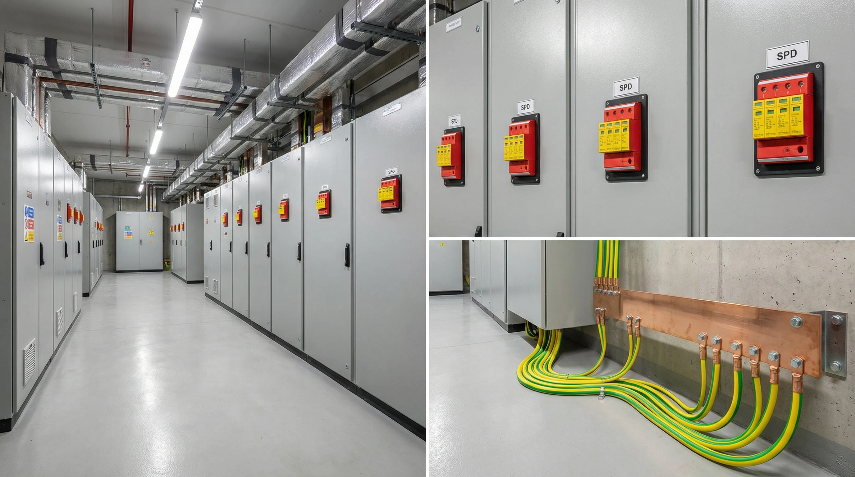
Figure 3.1: Commercial Building Lightning Protection Configuration
| Parameter | Specification |
|---|---|
| Voltage Level | 10kV/0.4kV, TN-S system |
| Service Entrance SPD | Type 1, In=12.5kA (10/350μs), Up≤2.5kV |
| Distribution SPD | Type 2, In=10kA (8/20μs), Up≤2.0kV |
| Grounding Resistance | ≤4Ω (general), ≤1Ω (IT equipment areas) |
| Protection Level | LPL III per GB 50057 |
3.2 Data Centers
Data centers demand the highest protection levels due to sensitive IT equipment and continuous operation requirements. Multi-level SPD cascades (Type 1 at service entrance with In=20kA, Type 2 at UPS input with In=20kA, Type 3 at rack PDUs with In=5kA) provide comprehensive defense. Grounding resistance must achieve ≤1Ω with mesh grounding networks under raised floors. Equipotential bonding integrates all metallic infrastructure including cable trays, HVAC ducts, and structural steel to prevent ground potential rise during lightning events.
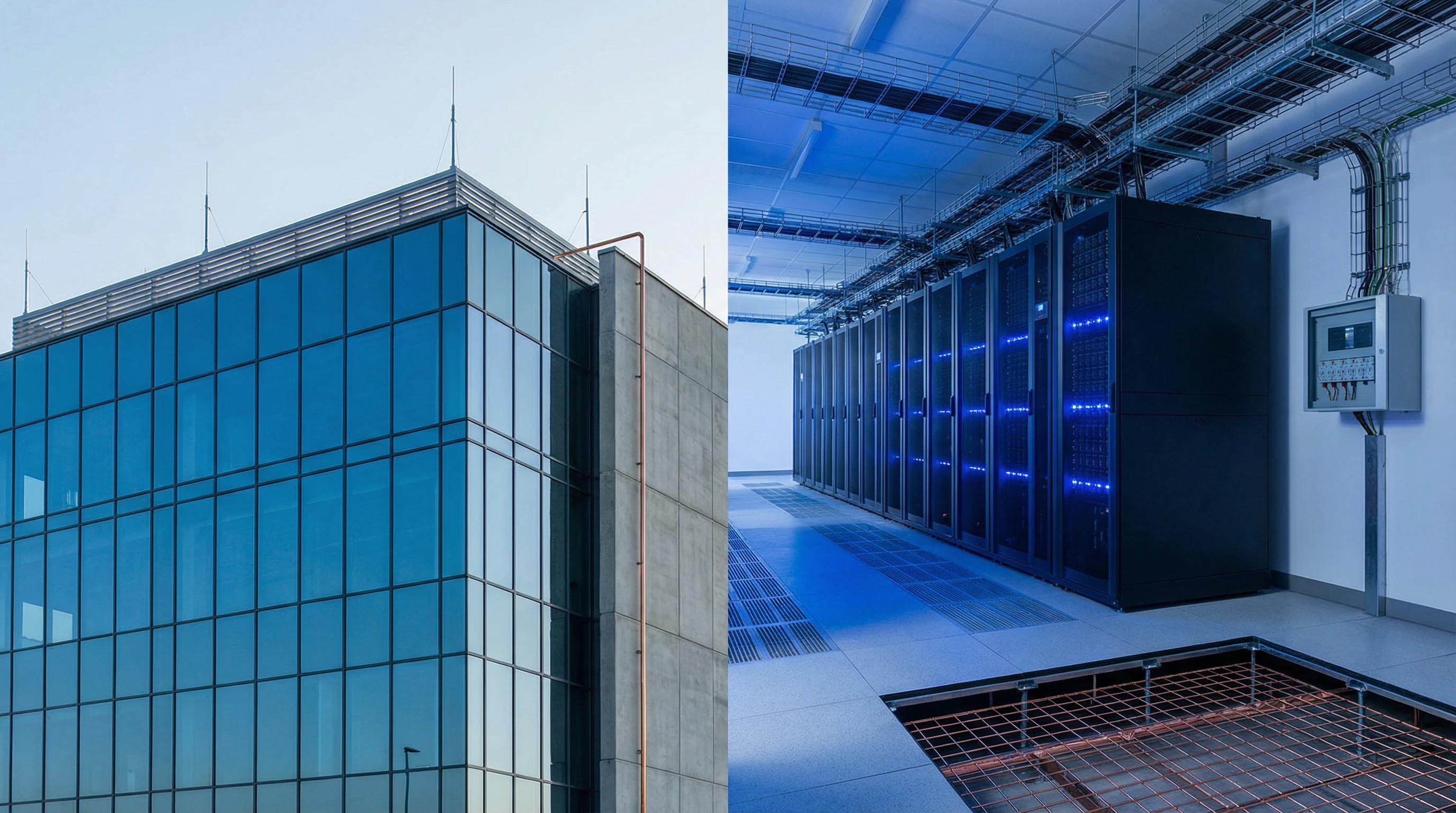
Figure 3.2: Data Center Lightning Protection and Grounding Infrastructure
| Parameter | Specification |
|---|---|
| Voltage Level | 10kV/0.4kV, dual-feed with ATS |
| Service Entrance SPD | Type 1, In=20kA (10/350μs), Up≤2.5kV |
| UPS Input SPD | Type 2, In=20kA (8/20μs), Up≤1.5kV |
| Equipment SPD | Type 3, In=5kA (8/20μs), Up≤1.2kV |
| Grounding Resistance | ≤1Ω with mesh network |
| Protection Level | LPL I-II per GB 50057 |
3.3 Industrial Manufacturing Facilities
Industrial plants with motor control centers, PLCs, and process control systems require robust protection against both direct strikes and conducted surges. SPD selection emphasizes high discharge current capacity (Type 1 with In=25kA at service entrance) to handle severe lightning exposure in open industrial areas. Grounding systems integrate process equipment grounding with building grounding to maintain equipotential conditions. Special attention addresses protection of variable frequency drives and instrumentation circuits sensitive to transient overvoltages.
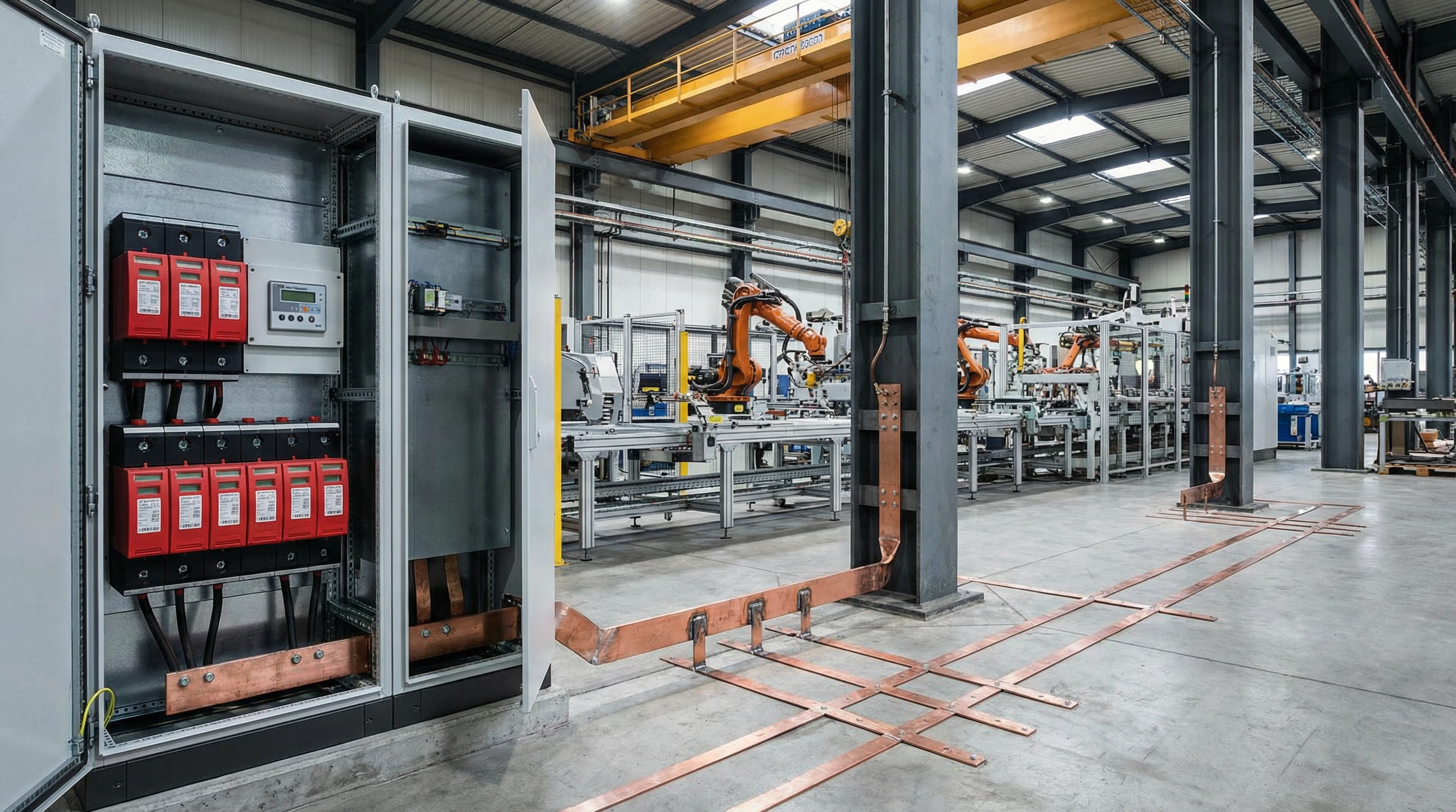
Figure 3.2: Industrial Manufacturing Facility Protection Architecture
| Parameter | Specification |
|---|---|
| Voltage Level | 10kV/0.4kV, multiple transformers |
| Service Entrance SPD | Type 1, In=25kA (10/350μs), Up≤2.5kV |
| MCC SPD | Type 2, In=15kA (8/20μs), Up≤2.0kV |
| Instrumentation SPD | Type 3, In=5kA (8/20μs), Up≤1.2kV |
| Grounding Resistance | ≤4Ω (power), ≤1Ω (control systems) |
| Protection Level | LPL II-III per GB 50057 |
3.4 Telecommunications Base Stations
Telecom sites face unique challenges from tower-mounted antennas attracting lightning strikes and sensitive RF equipment requiring clean power. Protection architecture combines external lightning protection for towers with coordinated SPDs on AC power (Type 1+2 combined, In=20kA), DC power (-48V systems, specialized DC SPDs), and signal lines (coaxial and fiber interface protection). Grounding resistance targets ≤5Ω for tower grounding integrated with equipment grounding through single-point grounding schemes to avoid ground loops.
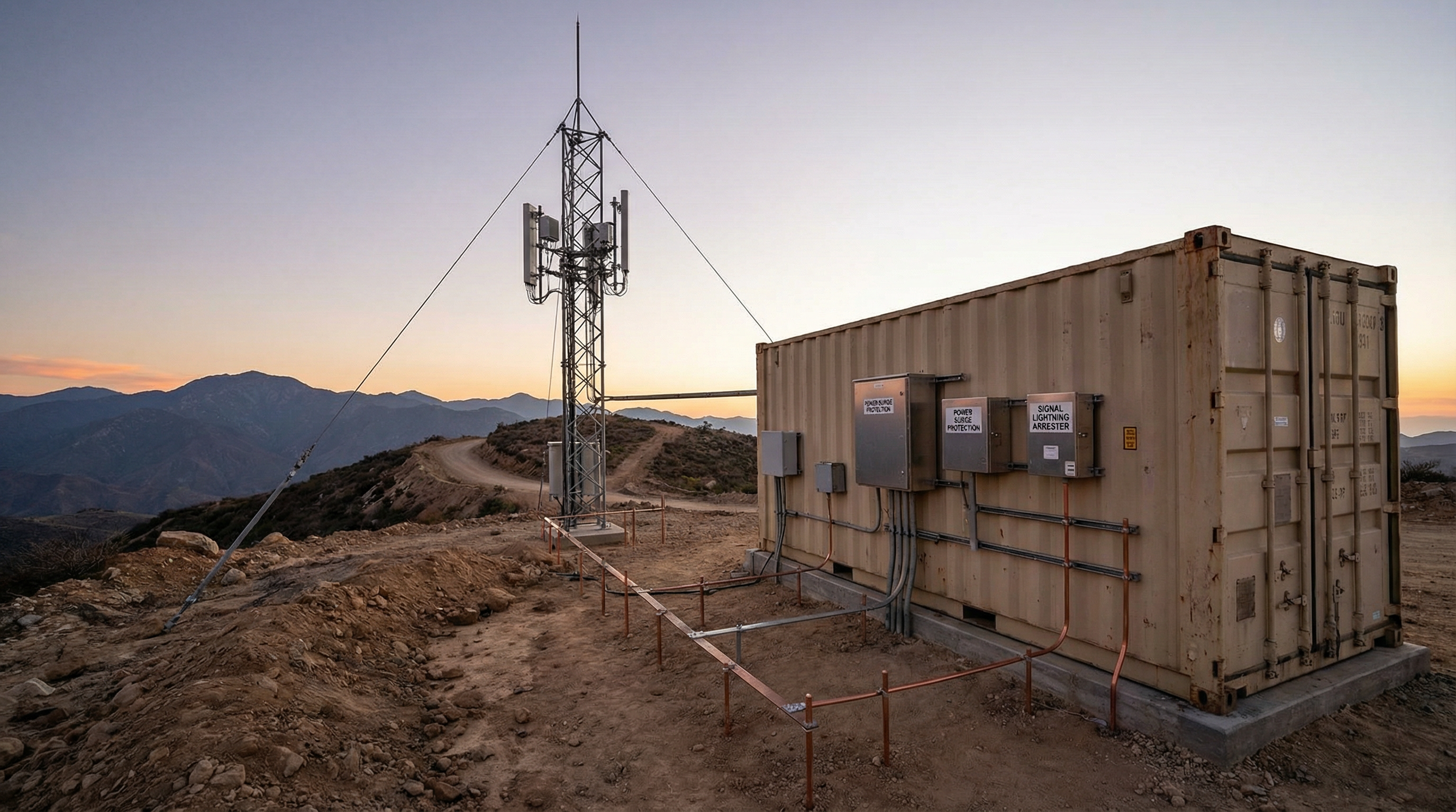
Figure 3.3: Telecommunications Base Station Lightning Protection System
| Parameter | Specification |
|---|---|
| Voltage Level | 0.4kV AC + -48V DC systems |
| AC Power SPD | Type 1+2 combined, In=20kA, Up≤2.0kV |
| DC Power SPD | Specialized -48V DC, In=10kA, Up≤100V |
| Signal Line SPD | Coaxial and data line protection |
| Grounding Resistance | ≤5Ω (tower and equipment unified) |
| Protection Level | LPL II per GB 50057 |
3.5 Healthcare Facilities
Hospitals and medical centers require uninterrupted power for life-safety systems and sensitive diagnostic equipment. Lightning protection emphasizes continuity with redundant SPD installations and isolated grounding for medical equipment per GB 16895.24. Critical areas including operating rooms, ICUs, and imaging centers receive enhanced protection with Type 2 SPDs (In=20kA) at distribution panels and Type 3 protection at equipment level. Grounding resistance maintains ≤1Ω for medical IT systems with careful attention to electromagnetic compatibility.
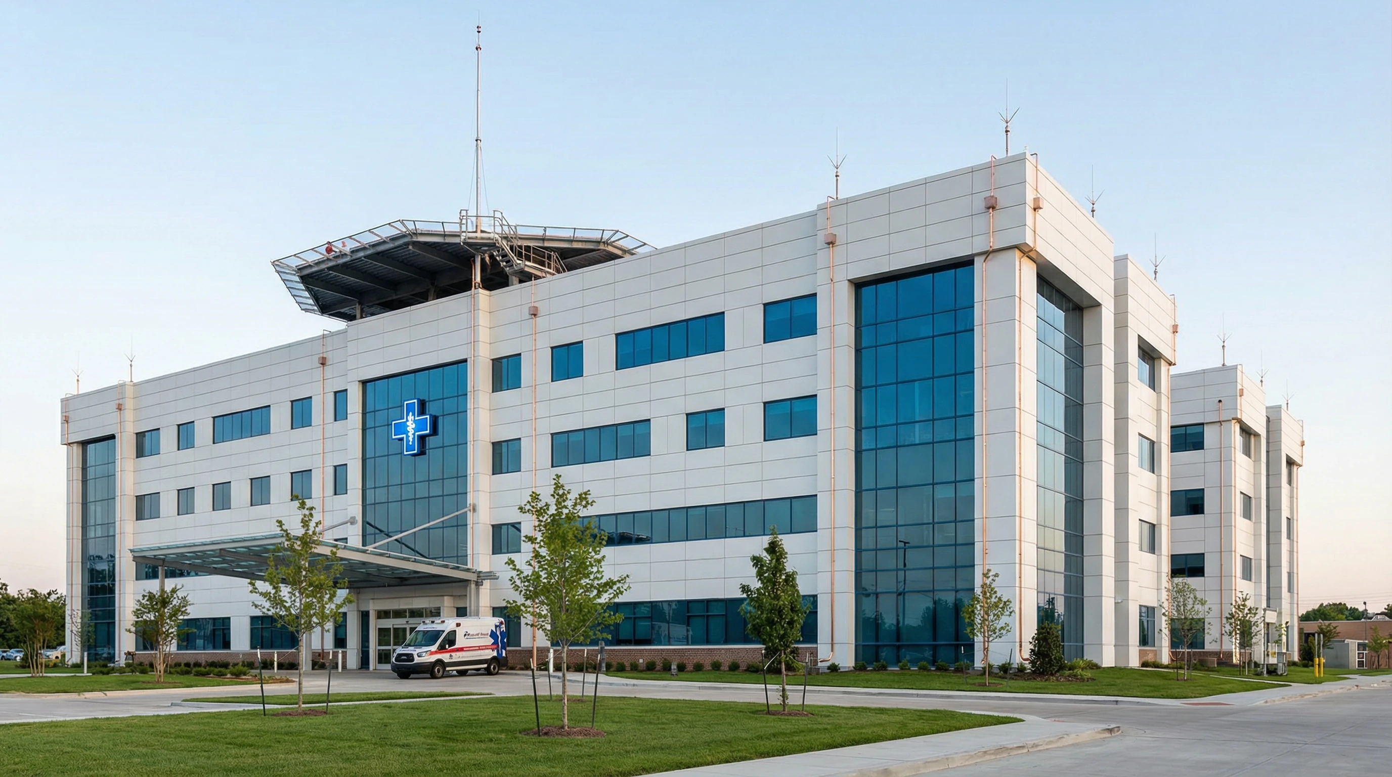
Figure 3.4: Healthcare Facility Lightning Protection Infrastructure
| Parameter | Specification |
|---|---|
| Voltage Level | 10kV/0.4kV with emergency generators |
| Service Entrance SPD | Type 1, In=20kA (10/350μs), Up≤2.5kV |
| Critical Area SPD | Type 2, In=20kA (8/20μs), Up≤1.5kV |
| Medical Equipment SPD | Type 3, In=5kA (8/20μs), Up≤1.0kV |
| Grounding Resistance | ≤1Ω with isolated medical grounding |
| Protection Level | LPL I-II per GB 50057 |
3.6 Educational Institutions
Schools and universities with distributed buildings require campus-wide lightning protection coordination. Each building receives appropriate protection based on occupancy and equipment sensitivity, with central administration and IT facilities receiving enhanced protection (LPL II) while classrooms and dormitories utilize standard protection (LPL III). Grounding systems interconnect buildings through buried conductors to maintain equipotential conditions across campus. SPD selection balances cost-effectiveness with adequate protection for computers, projectors, and laboratory equipment.

Figure 3.5: Educational Campus Lightning Protection Coordination
| Parameter | Specification |
|---|---|
| Voltage Level | 10kV/0.4kV, multiple substations |
| Administrative Building SPD | Type 1, In=15kA; Type 2, In=10kA |
| Classroom Building SPD | Type 1, In=12.5kA; Type 2, In=10kA |
| Laboratory SPD | Enhanced Type 2, In=15kA; Type 3 at equipment |
| Grounding Resistance | ≤4Ω (general), ≤1Ω (IT/lab areas) |
| Protection Level | LPL II (admin/IT), LPL III (general) |
3.7 Residential Buildings
Multi-family residential buildings utilize cost-effective lightning protection with emphasis on life safety and fire prevention. External protection employs air terminals on roof perimeter with down conductors integrated into building structure. Internal protection focuses on service entrance SPDs (Type 1+2 combined, In=12.5kA) with optional distribution-level protection for sensitive home electronics. Grounding leverages foundation reinforcement with supplemental electrodes to achieve ≤10Ω resistance per GB 50057 residential requirements.
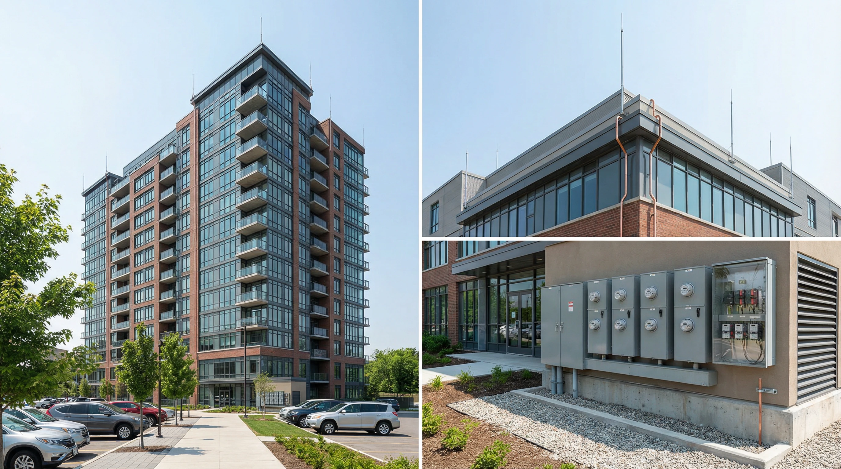
Figure 3.6: Residential Building Lightning Protection Configuration
| Parameter | Specification |
|---|---|
| Voltage Level | 0.4kV/0.23kV, TN-C-S system |
| Service Entrance SPD | Type 1+2 combined, In=12.5kA, Up≤2.5kV |
| Distribution SPD | Optional Type 2, In=5kA, Up≤2.0kV |
| Grounding Resistance | ≤10Ω per GB 50057 residential standard |
| Protection Level | LPL III-IV per GB 50057 |
3.8 Renewable Energy Installations
Solar photovoltaic and wind power installations face elevated lightning exposure due to open-field locations and elevated structures. Protection architecture addresses both AC and DC sides of power conversion systems with specialized SPDs rated for DC voltages up to 1000V and high discharge currents (In=20-40kA). Grounding systems integrate array frames, inverter enclosures, and tower structures with soil resistivity treatment often required in remote locations. String-level and inverter-level SPDs provide coordinated protection with careful attention to DC arc extinction capabilities.
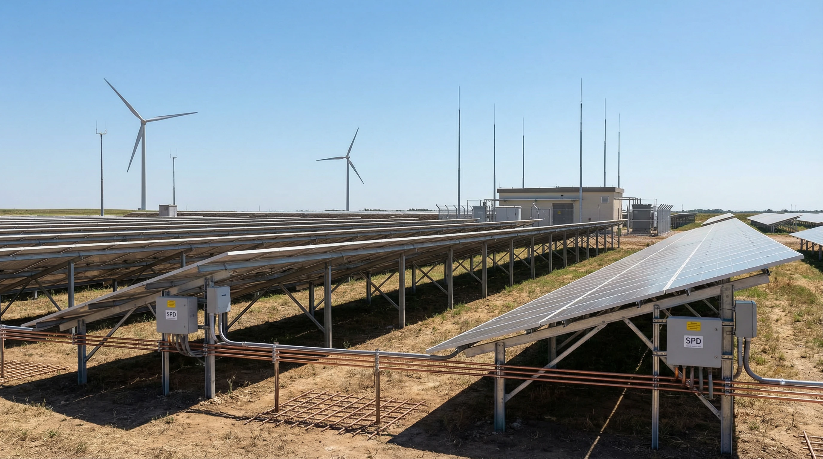
Figure 3.7: Renewable Energy Installation Lightning Protection Infrastructure
| Parameter | Specification |
|---|---|
| Voltage Level | DC 600-1000V (PV), AC 0.4-10kV (output) |
| DC Array SPD | Type 1+2, In=20-40kA, Uc=1000V DC |
| Inverter AC SPD | Type 2, In=20kA (8/20μs), Up≤2.0kV |
| Grounding Resistance | ≤4Ω with soil treatment if needed |
| Protection Level | LPL II per GB 50057 (elevated exposure) |
3.9 Selection Decision Framework
Systematic selection of lightning protection systems for low-voltage distribution applications follows a structured evaluation process considering facility characteristics, equipment sensitivity, regulatory requirements, and lifecycle costs. The decision framework guides procurement teams through risk assessment, protection level determination, component specification, and vendor evaluation to deliver optimal protection solutions.
Risk Assessment and Protection Level
Initial risk assessment per IEC 62305-2 evaluates lightning flash density, building dimensions, occupancy characteristics, and consequence of failure to determine required Lightning Protection Level (LPL I through IV). Critical facilities with sensitive equipment or life-safety implications typically require LPL I or II with enhanced protection measures, while general commercial and residential applications may utilize LPL III or IV with standard protection components. Assessment results establish grounding resistance targets, SPD specifications, and external protection requirements.
Component Specification Development
Component specifications derive from protection level requirements, system voltage, fault current levels, and equipment withstand characteristics. SPD specifications must address continuous operating voltage (Uc), nominal discharge current (In), maximum discharge current (Imax), voltage protection level (Up), and response time appropriate for each protection level. Grounding electrode specifications consider soil resistivity, available space, and target resistance values. Connection hardware specifications ensure adequate current-carrying capacity and corrosion resistance for the installation environment.
Vendor Evaluation and Procurement
Vendor evaluation criteria should emphasize product certification to applicable standards (IEC 61643 for SPDs, GB 50057 for external protection components), manufacturer quality management systems, technical support capabilities, and warranty provisions. Procurement specifications must mandate provision of type test reports, material certificates, and installation documentation. Total cost of ownership analysis should consider initial equipment costs, installation labor, maintenance requirements, and expected service life to identify optimal value propositions.