Selection and Interfaces
5.1 SPD Selection Methodology
Surge protective device selection requires systematic evaluation of electrical parameters, installation environment, and coordination requirements to ensure effective protection while maintaining system reliability. The selection process begins with determination of system voltage and protection level requirements, proceeds through parameter specification for each protection stage, and concludes with verification of coordination between levels. Proper selection balances protection effectiveness against cost, physical size, and maintenance requirements to deliver optimal value over the system lifecycle.
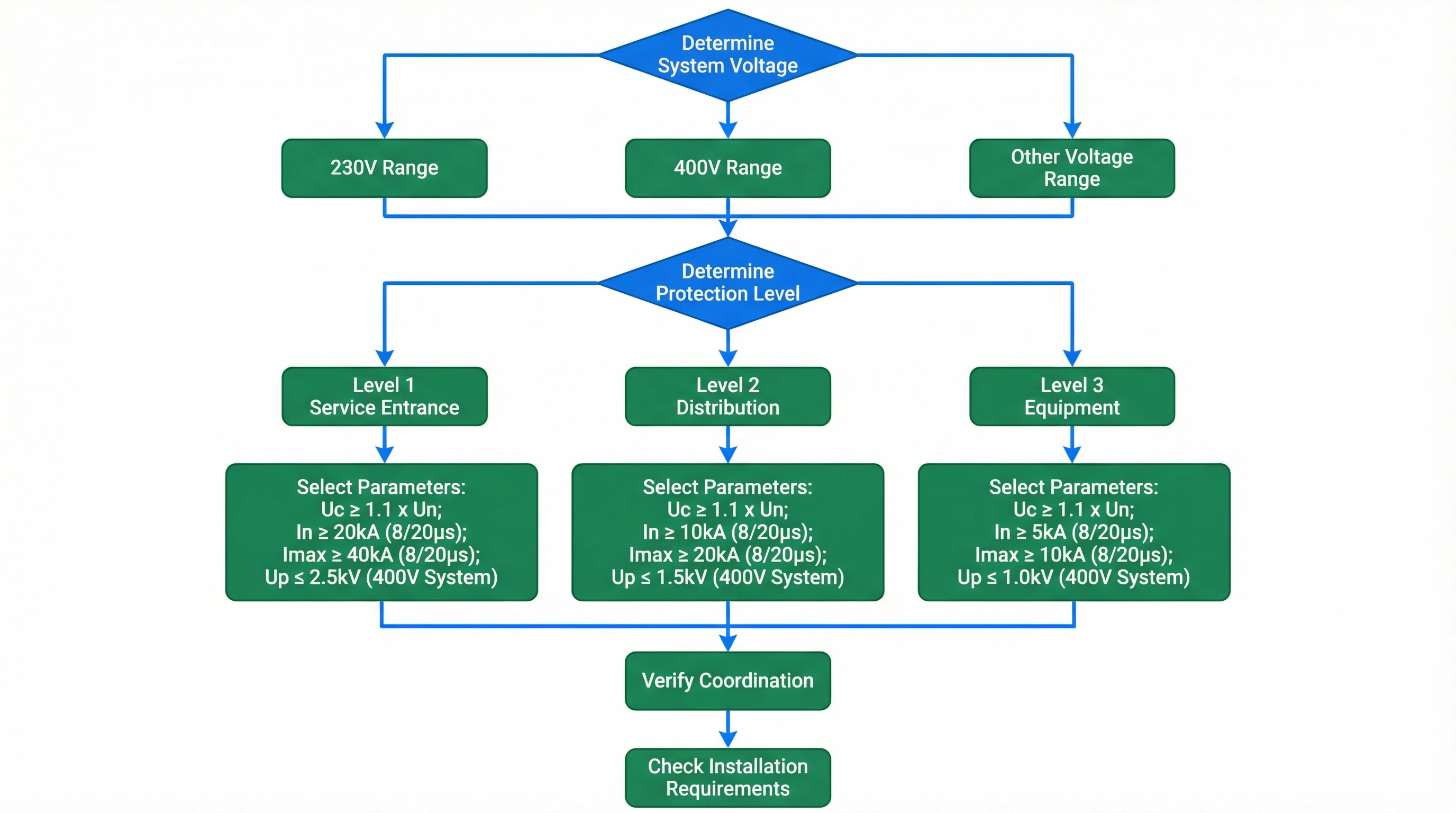
Figure 5.1: SPD Selection Decision Process Flowchart Showing Parameter Determination Steps
Voltage Rating Selection
The continuous operating voltage (Uc) rating must exceed the maximum continuous system voltage including normal variations and temporary overvoltages. For 230V single-phase systems, minimum Uc of 275V accommodates normal voltage tolerance and temporary overvoltages. Three-phase 400V systems require Uc ≥ 440V (line-to-neutral) or 760V (line-to-line). Systems with poor power quality or frequent voltage swells benefit from higher Uc ratings to prevent nuisance SPD operation or premature degradation.
Discharge Current Capacity
Nominal discharge current (In) and maximum discharge current (Imax) ratings determine the energy handling capability of the SPD. Level 1 devices require Imax ≥ 40kA (preferably 50-100kA) to withstand direct lightning current components, while Level 2 devices typically specify Imax of 20-40kA. Level 3 devices may employ lower Imax ratings (10-20kA) since upstream protection limits the energy reaching terminal equipment. The In rating (typically tested with 15-20 pulses) indicates the current level the device can withstand repeatedly without degradation.
Voltage Protection Level
The voltage protection level (Up) specifies the maximum voltage that will appear across the SPD terminals during operation, directly determining the stress applied to protected equipment. Level 1 SPDs may exhibit Up values of 2.5-4kV, acceptable for robust electrical equipment but excessive for sensitive electronics. Level 2 devices typically provide Up ≤ 1.5kV, while Level 3 devices should deliver Up ≤ 1.0kV for sensitive equipment protection. The effective protection level at equipment terminals must account for inductive voltage drop in connection conductors, emphasizing the importance of short, direct connections.
| System Type | Voltage | Level 1 Uc | Level 1 Imax | Level 1 Up | Level 2 Up | Level 3 Up |
|---|---|---|---|---|---|---|
| Single-phase | 230V | ≥ 275V | ≥ 40kA | ≤ 2.5kV | ≤ 1.5kV | ≤ 1.0kV |
| Three-phase | 400V | ≥ 440V (L-N) | ≥ 40kA | ≤ 2.5kV | ≤ 1.5kV | ≤ 1.0kV |
| Industrial | 480V | ≥ 550V (L-N) | ≥ 50kA | ≤ 3.0kV | ≤ 2.0kV | ≤ 1.2kV |
| DC Telecom | -48V | ≥ 60V | ≥ 20kA | ≤ 150V | ≤ 100V | ≤ 80V |
5.2 Grounding Electrode Selection
Grounding electrode selection must account for soil conditions, available installation space, target resistance values, and long-term reliability requirements. Different electrode types exhibit varying performance characteristics that make them suitable for specific applications and soil environments. Proper selection considers both initial installation cost and lifecycle costs including maintenance and replacement, recognizing that inadequate grounding represents a fundamental system weakness that compromises all other protection measures.
| Electrode Type | Construction | Typical Resistance | Advantages | Limitations | Best Applications |
|---|---|---|---|---|---|
| Copper-Bonded Steel Rod | Steel core with molecularly bonded copper layer, 1.5-3m length, 16-20mm diameter | 10-50Ω (single rod, typical soil) | Good conductivity, mechanical strength, cost-effective | Requires deep driving, performance varies with soil | General purpose, new construction |
| Solid Copper Rod | Pure copper construction, 1.5-3m length, 16-20mm diameter | 8-40Ω (single rod, typical soil) | Excellent conductivity, superior corrosion resistance | Higher cost, softer material complicates driving | Corrosive environments, critical facilities |
| Galvanized Steel Rod | Hot-dip galvanized steel, 1.5-3m length, 16-20mm diameter | 15-60Ω (single rod, typical soil) | Low cost, adequate for many applications | Limited corrosion protection, higher resistance | Budget-constrained projects, dry environments |
| Chemical/Ion Electrode | Perforated tube filled with conductive compound, 2-4m length | 5-20Ω (typical installation) | Effective in high-resistivity soil, stable long-term | Higher initial cost, requires compound replenishment | Rocky or sandy soil, space-constrained sites |
| Horizontal Conductor | Copper or galvanized steel strip/cable, 0.6-1.0m depth | Varies with length and soil (typically 1-10Ω per 100m) | Large earth contact area, accommodates building perimeter | Requires extensive excavation, shallow depth limits effectiveness | Building perimeter grounding, retrofit applications |
Electrode quantity and spacing calculations determine the number of electrodes required to achieve target resistance values while accounting for mutual interference between closely spaced electrodes. Parallel electrode resistance follows the formula Rtotal = R1/n × efficiency factor, where the efficiency factor accounts for mutual interference and typically ranges from 0.6-0.8 for electrodes spaced at 2-3 times their length. Verification measurements after installation confirm that design targets have been achieved and identify any installation defects requiring correction.
5.3 Connection and Interface Specifications
Electrical connections and interfaces represent critical points where improper design or installation can compromise system effectiveness. Connection quality directly impacts system resistance, reliability, and long-term performance, making proper specification and installation verification essential quality control points. Interface specifications must address both electrical performance requirements and mechanical reliability under environmental stress, vibration, and thermal cycling conditions.
SPD Connection Requirements
SPD connections must minimize total conductor length while providing adequate mechanical support and facilitating future replacement. The combined length of line, SPD, and ground connections should not exceed 0.5 meters to limit inductive voltage drop. Conductor cross-section must accommodate maximum expected surge current without excessive heating, typically requiring minimum 10mm² for Level 1 devices, 6mm² for Level 2, and 2.5mm² for Level 3. Connection terminals require proper torque application per manufacturer specifications to ensure low contact resistance without damaging terminals or conductors.
Grounding Conductor Connections
Grounding conductor connections employ exothermic welding, compression connectors, or bolted connections depending on conductor type and installation environment. Exothermic welding provides the most reliable long-term connection with resistance approaching that of solid conductor, making it preferred for buried connections and critical applications. Compression connections using hydraulic tools deliver reliable performance when properly installed with appropriate dies and adequate compression force. Bolted connections require proper surface preparation, anti-oxidant compound application, and specified torque values to ensure low resistance and prevent loosening under thermal cycling.
| Connection Type | Method | Typical Resistance | Advantages | Disadvantages | Recommended Use |
|---|---|---|---|---|---|
| Exothermic Weld | Chemical reaction creates molecular bond | < 0.01Ω | Permanent, lowest resistance, no maintenance | Requires training, consumable cost, not reversible | Buried connections, critical joints |
| Compression Lug | Hydraulic crimping of copper lug | < 0.02Ω | Reliable, inspectable, standard tooling | Requires proper die selection and crimping force | Above-ground connections, panel terminations |
| Bolted Connection | Mechanical clamping with torque specification | < 0.03Ω | Reversible, no special tools, field-adjustable | Requires maintenance, can loosen, corrosion risk | Accessible locations, temporary installations |
| Clamp Connection | Split clamp with bolts, no conductor preparation | < 0.05Ω | Fast installation, no conductor damage | Higher resistance, requires periodic tightening | Pipe bonding, temporary connections |
5.4 Signal Circuit Protection Selection
Signal circuit protection requires careful matching of SPD characteristics to circuit voltage levels, signaling methods, and bandwidth requirements. Unlike power circuit protection where voltage protection level represents the primary selection criterion, signal protection must balance surge suppression effectiveness against insertion loss, capacitance, and other parameters that could degrade signal quality. Proper selection ensures that protection devices remain transparent to normal signals while providing effective clamping of surge events.
Data Network Protection
Ethernet network protection must maintain Category 5e or Category 6 performance specifications including bandwidth to 100MHz or 250MHz respectively, while providing effective surge protection. SPDs for these applications typically employ gas discharge tubes for coarse protection combined with fast-responding suppressor diodes for fine protection, achieving voltage protection levels below 100V while maintaining insertion loss below 0.3dB. Power over Ethernet (PoE) applications require SPDs capable of passing DC power (up to 60W for PoE++) while protecting both power and data pairs.
Serial Data Protection
RS-232, RS-485, and other serial interfaces require protection devices compatible with circuit voltage levels and data rates. RS-232 circuits operating at ±12V require SPDs with appropriate voltage ratings and low capacitance to avoid limiting communication distance. RS-485 differential circuits benefit from common-mode and differential-mode protection, with common-mode protection clamping voltage between the data pair and ground while differential protection limits voltage between the two signal conductors. Maximum capacitance specifications (typically 50-100pF) ensure that protection does not limit network length or data rate.
Analog Signal Protection
Analog instrumentation circuits including 4-20mA current loops and 0-10V voltage signals require protection that maintains signal accuracy while providing surge suppression. Current loop protection must exhibit low series resistance to avoid introducing errors, while voltage signal protection requires high input impedance to prevent loading the signal source. Bidirectional protection devices accommodate signals that swing both positive and negative relative to ground, while unidirectional devices suit applications with defined signal polarity.