System Components
1.1 Functional Architecture
The Lightning Protection & Earthing (LPE) system comprises two primary subsystems that work in concert to provide comprehensive protection against lightning hazards. The External Lightning Protection Subsystem intercepts direct lightning strikes and safely conducts lightning current to earth, while the Internal Lightning Protection Subsystem mitigates induced overvoltages and electromagnetic interference within the facility. These subsystems integrate through a unified grounding network and equipotential bonding infrastructure to create a complete protection envelope.
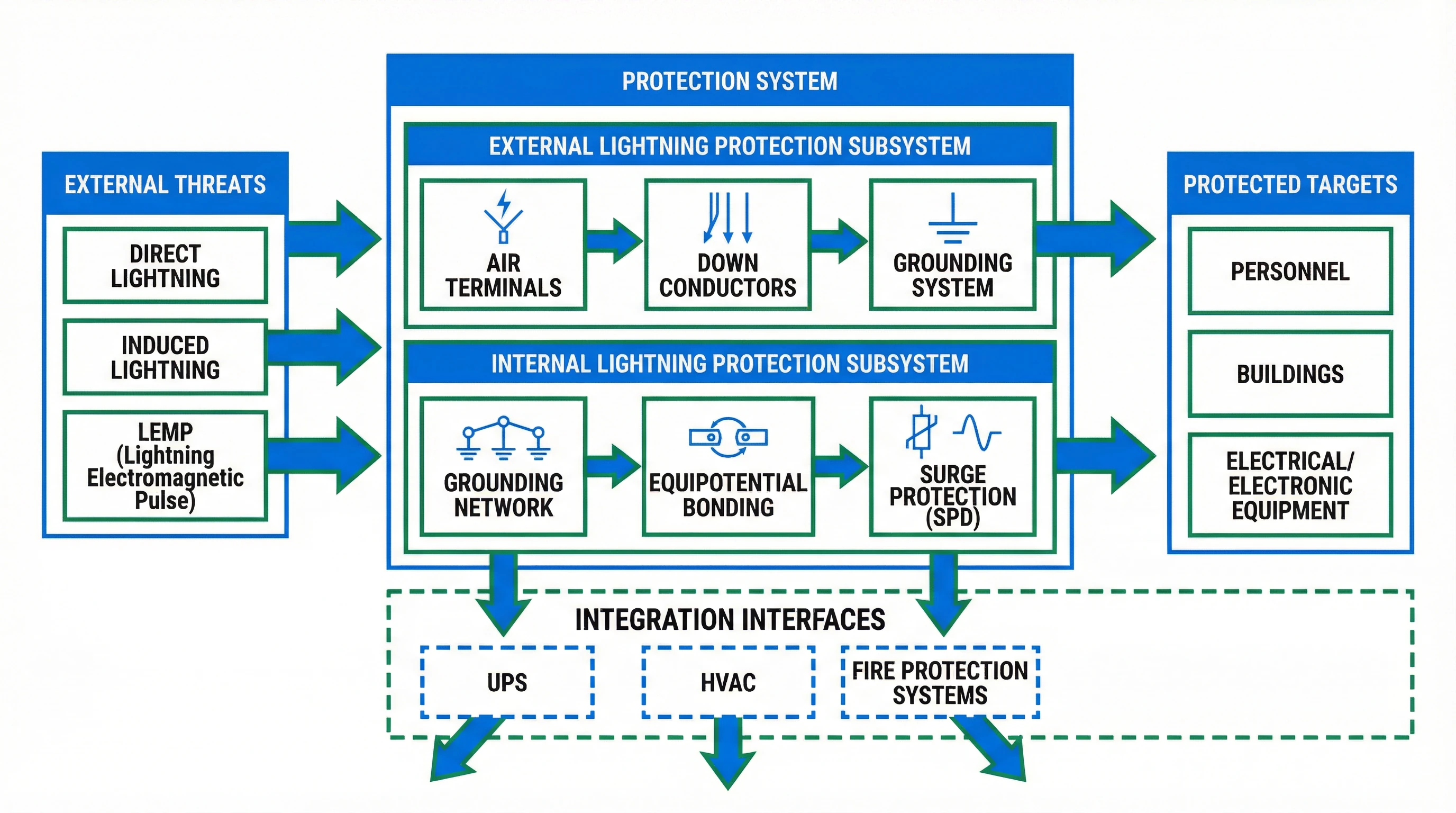
Figure 1.1: Lightning Protection & Earthing System Functional Architecture Block Diagram
The External Lightning Protection Subsystem consists of three fundamental components: air terminals (lightning rods, conductors, or meshes) positioned at elevated points to attract lightning strikes; down conductors that provide low-impedance paths for lightning current flow; and grounding systems that dissipate lightning energy into the earth. These components must be designed as an integrated system with proper spacing, cross-sectional areas, and connection methods to ensure reliable performance under extreme current conditions.
The Internal Lightning Protection Subsystem addresses the more subtle but equally dangerous threats of induced overvoltages and electromagnetic pulses. This subsystem employs a comprehensive grounding network that establishes a common reference potential throughout the facility, equipotential bonding that eliminates dangerous voltage differences between metallic components, and surge protective devices (SPDs) that clamp transient overvoltages to safe levels. The effectiveness of internal protection depends critically on proper coordination between these elements and their integration with external protection measures.
Integration interfaces connect the lightning protection system to other critical infrastructure including uninterruptible power supplies (UPS), heating ventilation and air conditioning (HVAC) systems, and fire protection systems. These interfaces require careful design to prevent lightning-induced disturbances from propagating between systems while maintaining necessary functional connections. Proper interface design ensures that lightning protection enhances rather than compromises the reliability of interconnected systems.
1.2 Key Components
The Lightning Protection & Earthing system relies on carefully selected components that must meet stringent performance, reliability, and compatibility requirements. Component selection directly impacts system effectiveness, operational lifespan, and maintenance requirements. Understanding the characteristics, applications, and quality indicators of each component category enables informed procurement decisions that balance initial costs against long-term value.
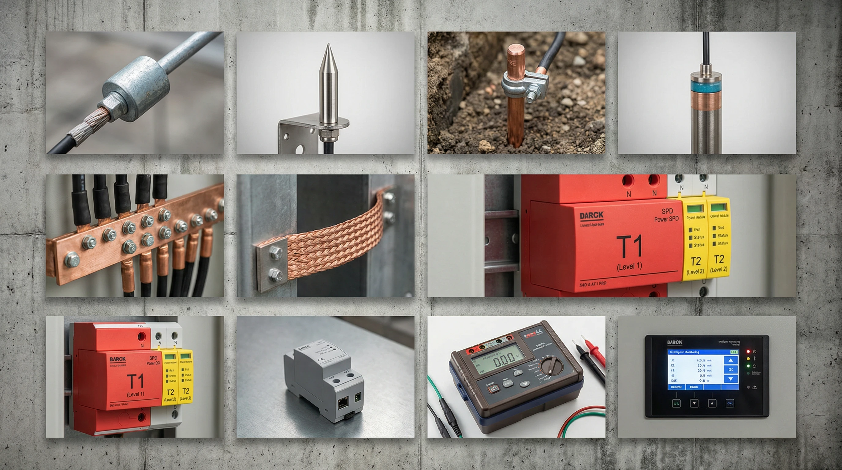
Figure 1.2: Lightning Protection & Earthing System Key Component Photographic Reference
External Protection Components
Air terminals serve as the primary interception points for direct lightning strikes. Franklin rod configurations utilize pointed conductors to create preferential strike points, while mesh conductor systems provide area protection through a network of interconnected conductors. Material selection typically favors galvanized steel for cost-effectiveness in standard applications, stainless steel for corrosive environments, and copper for premium installations requiring maximum conductivity and corrosion resistance. Critical quality factors include material purity, dimensional consistency, and surface treatment quality that determines long-term corrosion resistance.
Down conductors provide the critical current path between air terminals and grounding systems. These conductors must exhibit sufficient cross-sectional area to carry peak lightning currents without melting or sustaining damage, while maintaining mechanical strength to withstand electromagnetic forces during current flow. Galvanized round steel with minimum diameter of 8mm or galvanized flat steel with minimum cross-section of 40×4mm represents typical specifications for building applications. Installation practices must ensure continuous electrical connectivity through proper welding or mechanical connection techniques, with particular attention to avoiding sharp bends that could create high-impedance points or mechanical stress concentrations.
Grounding System Components
Grounding electrodes establish the physical connection between the lightning protection system and the earth mass. Copper-bonded steel rods combine the conductivity advantages of copper with the mechanical strength and cost-effectiveness of steel core construction, making them suitable for most soil conditions. Ion grounding electrodes incorporate specialized compounds that enhance soil conductivity in the immediate vicinity of the electrode, proving particularly valuable in high-resistivity soil environments. Electrode selection must account for soil resistivity, corrosion potential, available installation depth, and target resistance values, with proper installation techniques ensuring adequate electrode-to-soil contact and mechanical stability.
The Main Equipotential Bonding (MEB) terminal serves as the central connection point where all grounding conductors, metallic services, and protective earth conductors converge. This critical component must provide sufficient connection points for all required circuits while maintaining low contact resistance and mechanical reliability under thermal cycling and vibration conditions. Copper busbar construction with tin-plated surfaces represents the preferred implementation, with cross-sectional dimensions selected to accommodate maximum expected fault currents. Installation location should facilitate access for testing and maintenance while minimizing conductor lengths from connected systems.
Surge Protection Devices
Level 1 SPDs installed at service entrance points must withstand direct lightning current components, requiring robust construction with high discharge current capacity (Imax typically 50-100kA per mode). These devices typically employ spark gap or gas discharge tube technology to handle extreme energy levels, accepting higher voltage protection levels (Up) in exchange for superior energy handling capability. Installation requires coordination with upstream overcurrent protection and adequate separation from sensitive equipment to prevent coupling of residual overvoltages.
Level 2 SPDs provide intermediate protection at distribution boards, combining moderate energy handling capability (Imax typically 20-40kA) with improved voltage limiting performance. Metal oxide varistor (MOV) technology predominates at this level, offering fast response times and lower protection levels suitable for protecting most electrical equipment. Proper selection requires matching the continuous operating voltage (Uc) to system voltage characteristics while ensuring adequate energy coordination with both upstream Level 1 devices and downstream Level 3 protection.
Level 3 SPDs deliver fine protection for sensitive electronic equipment, prioritizing low protection levels (Up typically <1.5kV) over energy handling capacity. These devices install at equipment terminals or within sensitive circuits, utilizing fast-responding technologies such as suppressor diodes or hybrid configurations. Selection criteria emphasize compatibility with protected equipment voltage levels, minimal insertion loss for signal circuits, and appropriate response time for the protected application.
Testing and Monitoring Equipment
Earth resistance testers enable verification of grounding system performance through measurement of the resistance between grounding electrodes and remote earth. Three-pole and four-pole measurement methods eliminate the influence of test lead resistance, while clamp-on techniques permit testing without disconnecting grounding conductors. Measurement accuracy depends on proper electrode spacing, adequate soil moisture, and elimination of parallel paths that could yield misleadingly low readings. Regular calibration maintains measurement reliability essential for acceptance testing and periodic verification.
Intelligent monitoring terminals provide continuous surveillance of critical protection system parameters including SPD operational status, grounding resistance values, and lightning strike event counting. These devices integrate with building management systems to enable predictive maintenance strategies, immediate fault notification, and historical trend analysis. Implementation requires careful attention to communication protocol compatibility, power supply reliability, and protection of monitoring circuits themselves against lightning-induced disturbances that could compromise system availability.
1.3 Working Principles
Understanding the operational mechanisms of lightning protection and earthing systems enables effective design, proper installation, and informed troubleshooting. The system operates through coordinated interaction between multiple protection layers, each addressing specific aspects of the lightning threat. Normal operation maintains continuous monitoring and readiness, while lightning events trigger rapid protective responses that must complete within microseconds to prevent equipment damage.
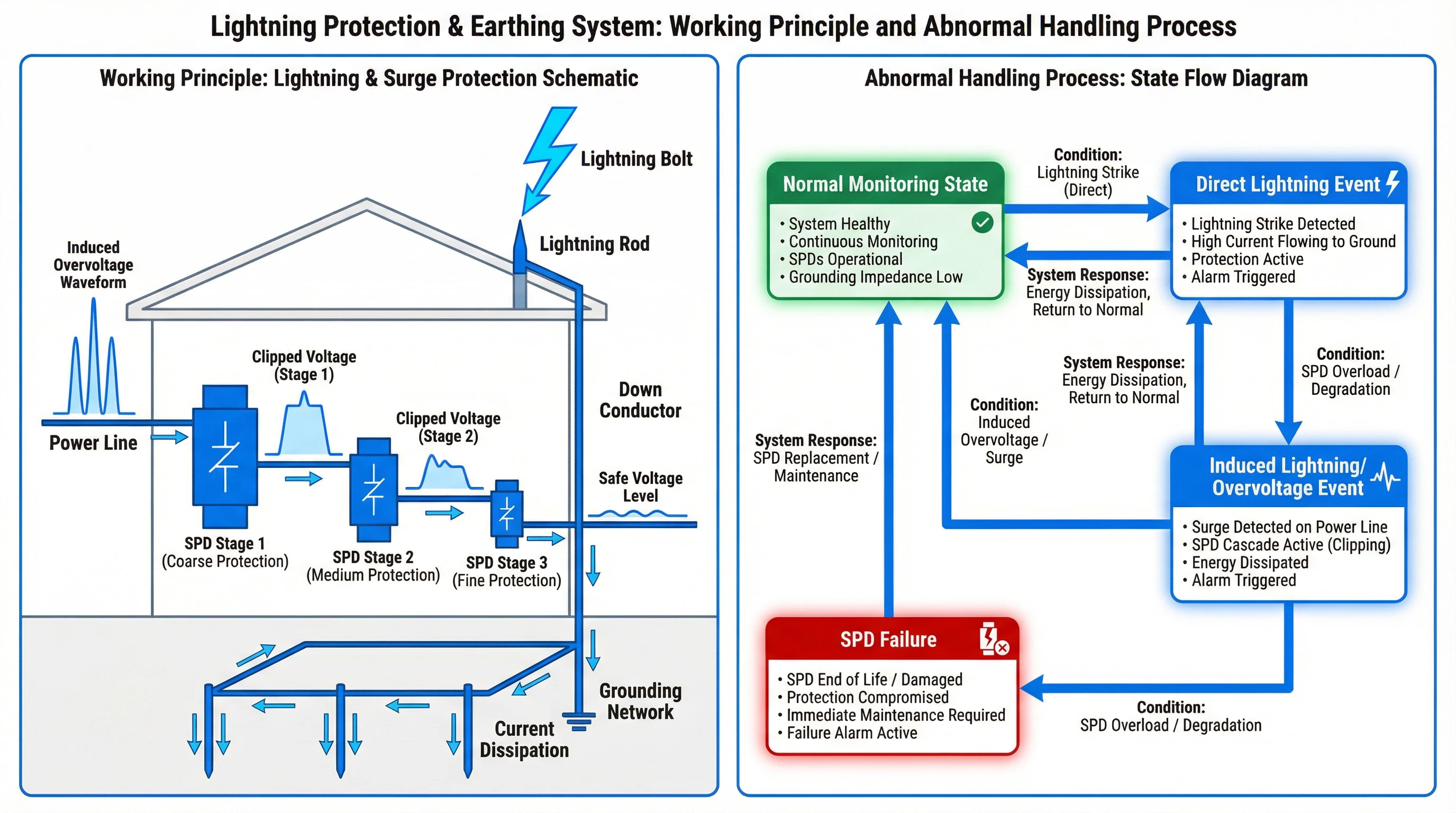
Figure 1.3: Lightning Protection & Earthing System Working Principle and Abnormal Handling Process
Direct Lightning Protection Mechanism
When a downward lightning leader approaches a protected structure, the air terminal system creates an upward connecting leader that intercepts the lightning channel before it can strike vulnerable building components or equipment. The rolling sphere method provides the theoretical basis for air terminal placement, ensuring that a sphere of specified radius (determined by protection level requirements) rolling over the structure surface contacts only air terminals and not protected surfaces. Upon successful interception, lightning current flows through down conductors to the grounding system, with current division among multiple parallel paths reducing individual conductor stress.
The grounding system dissipates lightning energy into the earth mass through a combination of resistive and capacitive coupling mechanisms. During the initial microseconds of current flow, the grounding system acts primarily as a capacitor, storing charge in the soil volume surrounding grounding electrodes. As the lightning event progresses, resistive current flow dominates, with the grounding resistance determining the ground potential rise experienced by the entire facility. Effective grounding system design minimizes both the resistance value and the physical extent of elevated potential regions to reduce step and touch voltage hazards.
Surge Protection Operation
Surge protective devices operate through voltage-dependent impedance characteristics that transition from high impedance during normal operation to low impedance when confronted with overvoltage conditions. In the non-conducting state, SPDs present minimal loading to protected circuits, with leakage currents typically below 1mA. When line voltage exceeds the SPD voltage protection level, the device rapidly transitions to a conducting state, diverting surge current to the protective earth conductor while clamping the voltage across protected equipment to safe levels.
Cascaded SPD coordination ensures that each protection level operates within its design parameters while providing progressively lower residual voltages at successive stages. Level 1 devices activate first, limiting the energy reaching downstream protection. Adequate impedance between protection levels (achieved through conductor length or discrete impedance elements) ensures proper energy sharing and prevents downstream devices from conducting before upstream protection has clamped the surge. Following surge current cessation, SPDs must extinguish any power-frequency follow current to prevent sustained short-circuit conditions that would trip upstream overcurrent protection.
Equipotential Bonding Function
Equipotential bonding eliminates dangerous potential differences that would otherwise develop between separated metallic components during lightning events or power system faults. By establishing low-impedance connections between all metallic services, structural steel, equipment enclosures, and protective earth systems, bonding ensures that these elements rise and fall in potential together, preventing flashover or shock hazards. The effectiveness of equipotential bonding depends on connection impedance remaining sufficiently low at lightning current frequencies, requiring attention to both DC resistance and inductive reactance of bonding conductors.
Abnormal Condition Handling
The system maintains continuous monitoring during normal operation, with intelligent terminals surveying SPD status, grounding resistance values, and environmental conditions. Upon detecting a direct lightning strike, the system logs the event, verifies continued SPD functionality, and generates alerts if any protection component has degraded. Induced lightning or switching surge events trigger SPD operation without necessarily causing device degradation, though cumulative stress tracking enables predictive replacement before failure occurs. SPD failure conditions activate local visual indicators and remote alarms, prompting immediate maintenance response to restore full protection capability before subsequent lightning exposure.